Автор: Техническая команда Meitec
Рецензент: Специалист по светодиодным дисплеям
Категория: Основы продукта
Дата последнего обновления: Сентябрь 2026 года
Режим сканирования является распространённой характеристикой в техническом описании модуля светодиодного дисплея, однако это также один из параметров, который покупатели часто понимают неправильно.
Такие термины, как сканирование 1/4, сканирование 1/8, сканирование 1/16, сканирование 1/32 и статическое сканирование, описывают электрический способ управления светодиодами на модуле. Они не описывают напрямую разрешение изображения, частоту обновления или яркость, хотя режим сканирования влияет на эти три аспекта фактических характеристик отображения.
Покупателям, монтажникам и системным интеграторам полезно понимать режим сканирования, поскольку два светодиодных дисплея с одинаковым шагом пикселя и разрешением могут иметь различную архитектуру управления, что приводит к различиям в яркости, энергопотреблении, характеристиках обновления и применении с камерами.
В данном руководстве объясняется, что означает режим сканирования светодиодного дисплея, как работают различные коэффициенты сканирования, как сканирование связано с частотой обновления и градациями серого, а также что следует учитывать при сравнении технических характеристик светодиодных дисплеев.
Что означает режим сканирования на светодиодном дисплее?
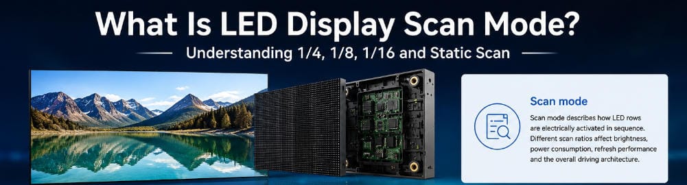
Модуль светодиодного дисплея содержит тысячи красных, зелёных и синих светодиодов, управляемых драйверными микросхемами.
Постоянное управление каждым светодиодом через выделенный электрический канал потребовало бы большого количества выходов драйверов и значительно усложнило бы конструкцию модуля.
По этой причине во многих светодиодных дисплеях используется метод, известный как мультиплексное сканирование..
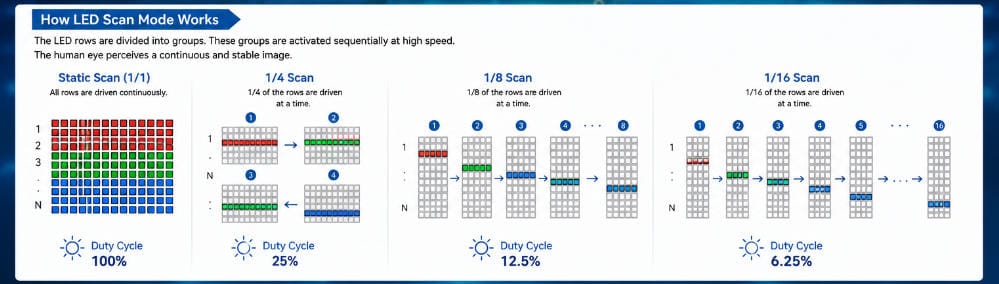
Вместо одновременного постоянного питания всех строк светодиодов система управления разделяет модуль на группы. Эти группы активируются последовательно с очень высокой скоростью.
Человеческий глаз обычно не воспринимает это переключение, поскольку полный цикл сканирования происходит чрезвычайно быстро. Поэтому экран выглядит непрерывно освещённым.
Коэффициент сканирования показывает, какая доля строк светодиодов активно управляется в течение одного шага сканирования.
Типичные примеры включают:
- Статическое сканирование
- Сканирование 1/2
- Сканирование 1/4
- Сканирование 1/8
- Сканирование 1/16
- Сканирование 1/32
- Сканирование 1/64
Подходящая конфигурация сканирования зависит от конструкции модуля, шага пикселя, архитектуры драйверных микросхем, требований к яркости и области применения.
Как работает сканирование светодиодного дисплея?
Упрощённый пример облегчает понимание принципа.
Представьте модуль светодиодного дисплея, пиксели которого разделены на 16 групп строк.
В конфигурации сканирования 1/16, только одна из этих 16 групп активно управляется в течение конкретного периода сканирования.
Драйверная микросхема активирует первую группу, затем вторую, затем третью, продолжая до тех пор, пока не будут адресованы все 16 групп.
После этого процесс начинается заново.
Весь этот цикл повторяется много раз в секунду.
Таким образом, светодиоды не обязательно светятся непрерывно. Вместо этого они получают короткие электрические импульсы, которые возникают достаточно часто, чтобы создать восприятие стабильного изображения.
Такая мультиплексная архитектура сокращает количество требуемых каналов драйверов и позволяет производителям создавать компактные светодиодные модули с высокой плотностью пикселей.
Что означает сканирование 1/4?
Модуль светодиодного дисплея со сканированием 1/4 разделяет свои светодиоды на четыре группы сканирования.
На любом данном шаге сканирования активно управляется примерно одна четверть соответствующих строк светодиодов.
Затем драйвер переключается между четырьмя группами.
По сравнению с более высоким коэффициентом мультиплексирования, таким как сканирование 1/16 или 1/32, сканирование 1/4 обычно позволяет каждой группе светодиодов иметь больше активного времени в течение одного полного цикла сканирования.
Это может способствовать поддержанию более высокой яркости, и это одна из причин, по которой относительно низкие коэффициенты сканирования часто встречаются в наружных светодиодных дисплеях.
Однако фактические характеристики по-прежнему зависят от эффективности светодиодов, драйверных микросхем, настроек тока и конструкции модуля.
Что означает сканирование 1/8?
В конфигурации сканирования 1/8 модуль разделяется на восемь групп сканирования.
Каждая группа получает часть общего времени управления.
Сканирование 1/8 часто встречается в различных модулях светодиодных дисплеев, поскольку оно обеспечивает практичный компромисс между сложностью схемы, яркостью и загрузкой драйверов.
Например, в некоторых конфигурациях наружных светодиодных дисплеев используются коэффициенты сканирования около 1/8 или ниже в зависимости от шага пикселя и конструкции корпуса светодиода.
Коэффициент сканирования следует оценивать как часть архитектуры модуля, а не как независимый показатель качества изображения.
Что означает сканирование 1/16?
Модуль со сканированием 1/16 имеет 16 последовательных групп управления.
По сравнению со сканированием 1/4 или 1/8, каждая отдельная группа получает меньшую долю общего периода сканирования.
Более высокие коэффициенты мультиплексирования могут уменьшить количество требуемых выходов драйвера для заданного числа светодиодов, что становится особенно полезным по мере увеличения плотности пикселей.
Именно поэтому коэффициенты сканирования, такие как 1/16, 1/32 или выше, часто ассоциируются с indoor-модулями и модулями с малым шагом пикселя.
Однако более высокий знаменатель сканирования также предъявляет повышенные требования к системе драйверов.
Архитектура управления светодиодами должна обеспечивать достаточную яркость, производительность обновления и точность градаций серого, даже несмотря на относительно короткий активный период каждой группы сканирования.
Что такое статическое сканирование?
Статическое сканирование принципиально отличается от мультиплексированного сканирования.
В конфигурации со статическим управлением каждый светодиод или пиксельный канал может непрерывно управляться, а не разделять время управления между несколькими группами сканирования.
Упрощенно:
Статическое сканирование = сканирование 1/1.
Это обеспечивает очень высокий коэффициент заполнения и может поддерживать отличные показатели яркости.
Поэтому статическое управление часто ассоциируется с определенными outdoor-светодиодными экранами, где высокая светимость особенно важна.
Обратной стороной является то, что статическое управление требует большего количества каналов драйвера и дополнительных схем по сравнению с мультиплексированными конструкциями.
По этой причине статическое сканирование не всегда является наиболее подходящей архитектурой для каждого светодиодного дисплея.
Также необходимо учитывать размер модуля, шаг пикселя, конструкцию питания, рассеивание тепла, тип светодиодов и общую стоимость системы.
Коэффициент сканирования и коэффициент заполнения
Режим сканирования тесно связан с коэффициентом заполнения.
Упрощенный способ понимания этой взаимосвязи:
Меньший знаменатель мультиплексирования = больше доступного активного времени для каждой группы сканирования.
Например:
| Режим сканирования | Упрощенная активная доля |
|---|---|
| Статический / 1/1 | 100% |
| Сканирование 1/2 | 50% |
| Сканирование 1/4 | 25% |
| Сканирование 1/8 | 12.5% |
| Сканирование 1/16 | 6.25% |
| Сканирование 1/32 | 3.125% |
Эти проценты помогают объяснить основную концепцию, но их не следует использовать для прямого расчета реальной яркости светодиодов.
Современные драйверные ИС для светодиодов используют сложное управление током, ШИМ-тайминг и поведение гашения. Оптический выход готового дисплея, таким образом, зависит от гораздо большего, чем номинальный коэффициент сканирования.
Означает ли более низкий коэффициент сканирования более яркий светодиодный дисплей?
Это может способствовать более высокой яркости, но данная взаимосвязь не является абсолютной.
Например, модуль со сканированием 1/4 предоставляет каждой группе сканирования больше доступного времени управления, чем модуль со сканированием 1/16.
При прочих аналогичных условиях это может облегчить достижение высокой светимости.
Это одна из причин, по которой outdoor-светодиодные экраны часто используют относительно низкие коэффициенты сканирования.
Однако яркость также зависит от:
- Эффективности светодиодных чипов
- Типа корпуса светодиода
- Тока управления
- Конструкции драйверной ИС
- Электрических характеристик печатной платы
- Конфигурации источника питания
- Рассеивания тепла
- Настроек калибровки
Таким образом, профессионально спроектированный модуль со сканированием 1/16 может превзойти плохо спроектированный модуль со сканированием 1/8.
Режим сканирования никогда не следует использовать в качестве единственного предиктора яркости дисплея.
Режим сканирования и частота обновления
Частоту сканирования и частоту обновления часто путают, поскольку обе описывают временные параметры внутри системы управления светодиодами.
Это не одна и та же характеристика.
Режим сканирования описывает, как мультиплексируются строки или группы светодиодов.
Частота обновления описывает, как часто светодиодный дисплей завершает свое электронное обновление в течение одной секунды.
Частота обновления обычно выражается в герцах, например:
- 1920 Гц
- 3840 Гц
- 7680 Гц
Режим сканирования выражается в виде соотношения, например:
- Сканирование 1/8
- Сканирование 1/16
- Сканирование 1/32
Два светодиодных модуля могут работать на частоте 3840 Гц, используя при этом различные коэффициенты сканирования.
Аналогично, два модуля с режимом сканирования 1/16 могут поддерживать разные частоты обновления в зависимости от используемых драйверных микросхем и конфигурации управления.
Для более подробного объяснения этого различия см. руководство компании Meitec Что такое частота обновления светодиодного дисплея? Руководство.

Как режим сканирования влияет на производительность обновления
Хотя режим сканирования и частота обновления являются отдельными параметрами, они взаимодействуют между собой.
В течение каждого цикла сканирования драйверная микросхема должна выполнить несколько задач за ограниченное время:
- Выбрать правильную строку сканирования
- Передать данные пикселей
- Управлять током светодиодов
- Формировать градации серого с помощью ШИМ
- Управлять периодами гашения
- Завершить достаточное количество циклов для поддержания заданной частоты обновления
По мере увеличения коэффициента мультиплексирования доступное временное окно для каждой группы сканирования становится короче.
Достижение высокой частоты обновления в сочетании с высокой глубиной градаций серого и стабильной работой при низкой яркости становится более требовательным.
Именно поэтому качество драйверной микросхемы и конструкция модуля особенно важны для светодиодных дисплеев с высокой плотностью пикселей.
Простое указание “3840 Гц” не раскрывает, насколько успешно вся система управления работает в реальных условиях эксплуатации.
Режим сканирования и градации серого
Градации серого описывают, сколько уровней яркости светодиодный дисплей может воспроизвести между черным и полной яркостью.
Типичные профессиональные светодиодные дисплеи могут указывать глубину градаций серого, такую как 13-бит, 14-бит, 16-бит или более высокие уровни обработки.
Режим сканирования напрямую не определяет глубину градаций серого, но сканирование consumes часть временного ресурса, доступного драйверной микросхеме.
В то же время драйвер должен формировать точные ШИМ-импульсы для воспроизведения различных уровней яркости.
Когда временные ограничения становятся все более жесткими, поддержание очень точной передачи градаций серого — особенно при низкой яркости экрана — требует более совершенной архитектуры драйвера.
Это имеет значение в таких применениях, как:
- Телевизионные студии
- Диспетчерские
- Корпоративные презентационные пространства
- Виртуальное производство
- Высококлассные арендные мероприятия
- Мелкошаговые indoor-дисплеи
Поэтому такие применения следует оценивать с помощью реальных тестов изображения, а не только по коэффициенту сканирования.
Почему наружные светодиодные дисплеи часто имеют более низкое сканирование?
Наружные дисплеи обычно требуют значительно более высокой яркости, чем indoor-дисплеи.
Экран, установленный на фасаде здания или придорожном рекламном щите, должен оставаться видимым при сильном окружающем освещении, а иногда и под прямыми солнечными лучами.
По этой причине наружные модули часто используют архитектуры, обеспечивающие относительно высокий коэффициент заполнения светодиодов.
Типичные конфигурации могут включать:
- Статический режим
- Сканирование 1/2
- Сканирование 1/4
- Сканирование 1/6
- Сканирование 1/8
Точное значение сильно зависит от шага пикселя и технологии светодиодов.
Например, Наружная серия Meitec MTO Pro использует различные режимы сканирования в диапазоне шагов пикселя. Текущие конфигурации включают сканирование 1/8, 1/7, 1/6, 1/4, 1/2 и статический режим, что иллюстрирует, почему режим сканирования должен подбираться под конкретный модуль, а не стандартизироваться для всей линейки продукции.
Почему мелкошаговые светодиодные дисплеи часто используют более высокие коэффициенты сканирования?
Мелкошаговые светодиодные дисплеи содержат очень большое количество пикселей на относительно небольшой физической площади.
По мере уменьшения шага пикселя плотность драйверов значительно возрастает.
Использование выделенных статических каналов управления для каждого светодиода сделало бы схему модуля чрезмерно сложной.
Более высокие коэффициенты мультиплексирования позволяют разработчикам распределять ресурсы драйверов между большим количеством строк светодиодов.
В результате indoor-дисплеи с мелким шагом могут использовать такие конфигурации, как:
- 1/16
- 1/20
- 1/32
- 1/40
- 1/64
Точная архитектура варьируется в зависимости от типа светодиодного корпуса, печатной платы, драйверной микросхемы и производителя.
Более высокий знаменатель сканирования не должен автоматически интерпретироваться как более низкое качество продукции. В инженерии светодиодных экранов с малым шагом пикселя это часто является практическим следствием значительно более высокой плотности пикселей.
Влияет ли режим сканирования на энергопотребление?
Архитектура сканирования может влиять на проектирование системы электропитания, однако не существует простого правила, согласно которому один коэффициент сканирования всегда потребляет больше электроэнергии, чем другой.
Фактическое энергопотребление зависит от нескольких переменных:
- Общее количество светодиодов
- Эффективность светодиодов
- Средний уровень изображения
- Настройка яркости дисплея
- Тока управления
- Архитектура с общим анодом или общим катодом
- Эффективность блока питания
- Потери в драйверных микросхемах
- Конфигурация сканирования
Более низкий коэффициент сканирования может обеспечивать более длительные периоды проводимости светодиодов, тогда как более высокое мультиплексирование может характеризоваться иным поведением пиковых токов.
Таким образом, итоговое измерение должно проводиться на основе полного модуля или шкафа, а не оцениваться исключительно по коэффициенту сканирования.
Влияет ли режим сканирования на работу камер?
Да, косвенно.
Камеры используют короткие периоды экспозиции, которые могут выявлять внутренние временные характеристики светодиодного дисплея.
Если камера фиксирует экран в момент, когда разные группы строк находятся на разных этапах последовательности сканирования, записанное изображение может содержать:
- Тёмные горизонтальные линии
- Яркие полосы
- Движущиеся линии сканирования
- Неравномерную экспозицию
- Частичное мерцание
Однако режим сканирования является лишь одной частью проблемы.
На работу камеры также влияют:
- Частота обновления светодиодов
- Частота ШИМ
- Драйверная микросхема
- Скорость затвора камеры
- Частота кадров камеры
- Настройка яркости
- Синхронизация
- Конфигурация системы управления
Это особенно важно для арендных светодиодных стен, используемых на концертах, выставках и в живых постановках, где экраны часто попадают в объективы профессиональных камер и смартфонов. Категория Арендный светодиодный дисплей компании Meitec охватывает продукты, предназначенные для таких временных мероприятий.
Для проектов, критически важных с точки зрения съёмки, тестирование фактического светодиодного модуля с предполагаемым камерным оборудованием остаётся более надёжным, чем выбор дисплея исключительно на основе заявленного коэффициента сканирования.
Всегда ли статическое сканирование лучше, чем сканирование 1/16 или 1/32?
Нет.
Статическое сканирование обеспечивает технические преимущества в приложениях, где требуется высокий коэффициент заполнения светодиодов, однако “более низкий коэффициент сканирования” не следует рассматривать как универсальный показатель качества.
Рассмотрим два гипотетических дисплея:
Дисплей A:
- P10 для наружного применения
- Статическое сканирование
- 8000 нит
Дисплей B:
- P1.25 для внутреннего применения
- Сканирование 1/32
- 800 нит
Дисплей со статическим сканированием значительно ярче, но это не делает его более качественным светодиодным дисплеем.
Оба продукта предназначены для совершенно разных условий эксплуатации.
Экран P1.25 ориентирован на очень высокую плотность пикселей и近距离观看距离. Экран P10 ориентирован на видимость при наружном применении.
Обе архитектуры сканирования, таким образом, могут быть технически приемлемыми.
Какой режим сканирования следует выбрать?
В большинстве случаев покупателям не следует выбирать светодиодный дисплей, сначала задавая коэффициент сканирования.
Вместо этого начните с области применения.
Наружная реклама
Приоритет следует отдавать:
- Требуемой яркости
- Защите окружающей среды
- Расстоянию просмотра
- Энергоэффективности
- Тепловым характеристикам
- Долгосрочной надежности
Более низкие коэффициенты сканирования или статическое управление являются распространенными, однако конечная конфигурация должна соответствовать конструкции модуля.
Внутренние коммерческие дисплеи
Приоритет следует отдавать:
- Шаг пикселя
- Расстоянию просмотра
- Равномерности изображения
- Глубина серого (градации серого)
- Соответствующей яркости
- Характеристикам обновления
Умеренные или более высокие коэффициенты мультиплексирования являются нормой.
Арендные и сценические светодиодные экраны
Приоритет следует отдавать:
- Совместимость с камерами
- Высокой частотой обновления
- Градации серого при низкой яркости
- Быстрый монтаж
- Механическая надежность
Конфигурация сканирования должна оцениваться совместно с драйверными ИС и характеристиками камеры.
Вещание и виртуальное производство
Приоритет следует отдавать всему рабочему процессу формирования изображения.
Коэффициента сканирования из технического описания недостаточно.
Профессиональная оценка может потребовать:
- Тестов с камерами
- Тестирования затвора
- Высокоскоростной записи
- Проверки синхронизации (Genlock)
- Тестов при низкой яркости
- Оценки градаций серого
Какие вопросы покупателям следует задавать поставщику?
При рассмотрении технических характеристик светодиодного дисплея полезными техническими вопросами являются:
- Какой режим сканирования используется в фактическом модуле?
- Какая драйверная ИС установлена?
- Какая частота обновления поддерживается в производственной конфигурации?
- Какая производительность по градациям серого доступна при низкой яркости?
- Измеряется ли заявленная яркость с использованием той же конфигурации сканирования?
- Может ли поставщик предоставить видеоматериалы тестирования с камерой?
- Основаны ли характеристики на стандартном продукте или на дополнительной конфигурации?
- Повлияет ли изменение настроек обновления или градаций серого на яркость?
Эти вопросы дают гораздо более точное представление о характеристиках дисплея, чем сравнение только коэффициентов сканирования.
Распространенные заблуждения о режиме сканирования светодиодных дисплеев
“Сканирование 1/8 вдвое лучше, чем сканирование 1/16”.”
Нет.
Эти два коэффициента описывают различные архитектуры мультиплексирования. Они не являются показателями качества.
“Статическое сканирование всегда обеспечивает наилучшее изображение”.”
Не обязательно.
Статическое сканирование полезно для определённых конструкций модулей, особенно для ярких уличных применений, однако мелкошаговые indoor-дисплеи обычно требуют иных архитектур управления.
“Частота сканирования и частота обновления — это одно и то же”.”
Нет.
Частота сканирования описывает мультиплексирование строк. Частота обновления описывает электронную частоту обновления.
“Более высокий коэффициент сканирования означает, что экран будет мерцать”.”
Не автоматически.
Поведение мерцания зависит от всей системы управления, включая частоту обновления, характеристики ШИМ и временные параметры управления.
“Два светодиодных дисплея можно сравнивать только по коэффициенту сканирования”.”
Нет.
Шаг пикселя, тип светодиодов, яркость, частота обновления, градации серого, драйверные ИС, термодизайн, калибровка и целевое применение — всё это необходимо оценивать в совокупности.
Итоговый принцип выбора
Режим сканирования светодиодного дисплея следует понимать как часть электрической архитектуры управления модулем.
Более низкий коэффициент сканирования обычно предоставляет каждой группе светодиодов большую часть периода управления, что может поддерживать приложения с высокой яркостью.
Более высокий коэффициент мультиплексирования позволяет большему числу светодиодов совместно использовать ресурсы драйверов и особенно полезен при увеличении плотности пикселей.
Ни один из подходов не является автоматически лучшим.
Правильная архитектура сканирования зависит от баланса между:
- Шаг пикселя
- Плотностью пикселей
- Яркость
- Частоту обновления
- Глубина серого (градации серого)
- Возможностями драйверных ИС
- Энергопотребление
- Требованиями камер
- Сложностью модуля
- Среда применения
По этой причине профессиональный выбор светодиодного дисплея должен основываться на характеристиках полного модуля и кабинета, а не на одном изолированном параметре.
В компании Meitec режим сканирования рассматривается как одна из частей полной системы управления светодиодами. Практическая цель заключается не в достижении максимально низкого или высокого коэффициента сканирования, а в сочетании соответствующей архитектуры модуля, драйверной электроники и оптических характеристик для целевого применения.
Краткие ответы на вопросы
Что такое режим сканирования в светодиодном дисплее?
Режим сканирования описывает, как группы строк светодиодов электрически активируются последовательно. Распространённые конфигурации включают статическую, 1/4, 1/8, 1/16 и 1/32.
Что означает сканирование 1/16?
Модуль со сканированием 1/16 разделяет соответствующие светодиоды на 16 групп сканирования. Каждая группа управляется последовательно в течение одного полного цикла сканирования.
Является ли сканирование 1/8 лучше, чем 1/16?
Не обязательно. Сканирование 1/8 обеспечивает более высокий рабочий цикл, тогда как сканирование 1/16 может поддерживать конструкции модулей с более высокой плотностью. Подходящая конфигурация зависит от продукта и применения.
Что такое статическое сканирование?
Статическое сканирование, также называемое сканированием 1/1, управляет светодиодными каналами непрерывно, а не мультиплексирует их по нескольким группам сканирования.
Влияет ли режим сканирования на яркость светодиодного дисплея?
Он может влиять на яркость, поскольку коэффициент сканирования влияет на доступное время управления светодиодами. Однако эффективность светодиодов, ток, драйверные ИС и конструкция модуля также важны.
Является ли режим сканирования тем же самым, что и частота обновления?
Нет. Режим сканирования описывает мультиплексирование строк светодиодов, тогда как частота обновления описывает, как часто электронная система управления дисплеем обновляет изображение каждую секунду.
Какой режим сканирования лучше всего подходит для светодиодного дисплея?
Универсального лучшего режима сканирования не существует. Уличные дисплеи с высокой яркостью часто используют более низкие коэффициенты сканирования, тогда как indoor-дисплеи с высокой плотностью могут использовать более высокие коэффициенты мультиплексирования. Общая производительность системы важнее, чем сам коэффициент.