Author: Meitec Technical Team
Reviewed by: LED Display Product Specialist
Category: Product Basics
Last Updated: September 2026
An LED display module is a standardized display unit made up of LEDs, a printed circuit board (PCB), driver electronics, connectors, and supporting mechanical components. Multiple LED modules are installed together inside cabinets or display structures to form a complete LED screen.
In a conventional LED display, the module is the part that actually produces the visible image. Each module contains a fixed number of pixels arranged according to its pixel pitch and resolution. The control system sends image data to the module through receiving cards and driver circuits, while the power supply provides the low-voltage DC power required by the LEDs and electronics.
Understanding LED display modules is important because many key screen specifications—including pixel pitch, module resolution, scan mode, brightness, refresh performance, maintenance method, and protection level—are closely related to module design.
What Is Inside an LED Display Module?
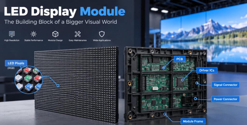
Although module construction varies between products, a typical LED display module contains several main components.
LED Pixels
The visible surface contains thousands of LED light-emitting elements arranged in a matrix.
In a full-color display, each pixel normally produces red, green, and blue light. By controlling the intensity of these three colors, the screen can reproduce a wide range of colors.
The physical distance between neighboring pixels is called pixel pitch.
For example:
- P1.25 = approximately 1.25 mm between pixel centers
- P2.5 = approximately 2.5 mm
- P4 = approximately 4 mm
- P10 = approximately 10 mm
Smaller pixel pitch increases pixel density and generally improves image detail at shorter viewing distances.
PCB
The printed circuit board provides the electrical connections between LEDs, driver ICs, power connections, and signal interfaces.
PCB design influences electrical stability, heat distribution, signal integrity, and module reliability.
Depending on the product, manufacturers may use different PCB layer structures, materials, copper thicknesses, and layouts according to current load, heat dissipation, pixel density, and application requirements.
Driver ICs
Driver ICs control the electrical current delivered to the LEDs.
They work with the receiving card and module circuit to determine when individual LED channels turn on and how strongly they illuminate.
Driver architecture can influence several display characteristics, including:
- Refresh rate
- Grayscale performance
- Brightness consistency
- Low-brightness image quality
- Scan configuration
- Power consumption
For this reason, two LED modules with the same pixel pitch may perform differently if their driver electronics and circuit designs are different.
Power and Signal Connectors
LED modules require both power and display data.
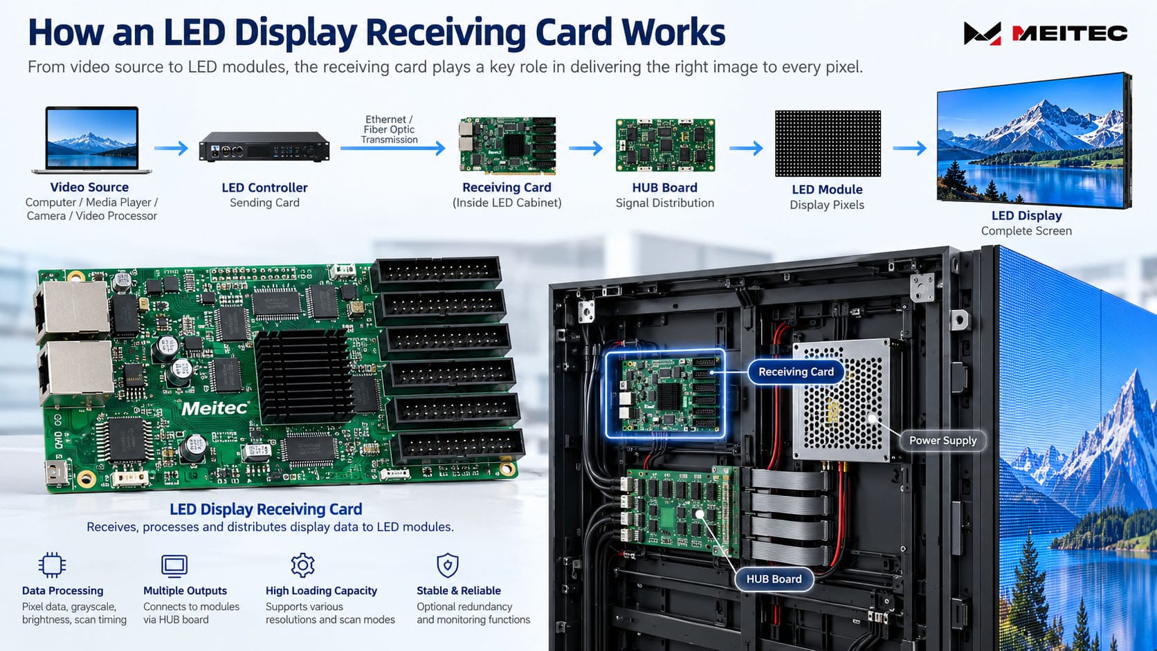
Power is normally supplied as low-voltage DC from power supplies installed inside the display cabinet. Signal data reaches the modules through a receiving card and, in many systems, a HUB board or integrated distribution board.
For more detail about the signal side of the system, see Meitec’s guide to the LED display receiving card.
Module Frame or Bottom Shell
Many modules use a plastic or metal rear structure that supports the PCB and helps position the module accurately.
Outdoor modules may use a more enclosed structural design together with sealing materials to improve resistance to water and dust.
Some modern outdoor products use fully enclosed module structures to improve environmental protection and simplify independent module replacement.
How Does an LED Display Module Work?
An LED module does not create video content by itself.
It is the final display component in a larger control chain.
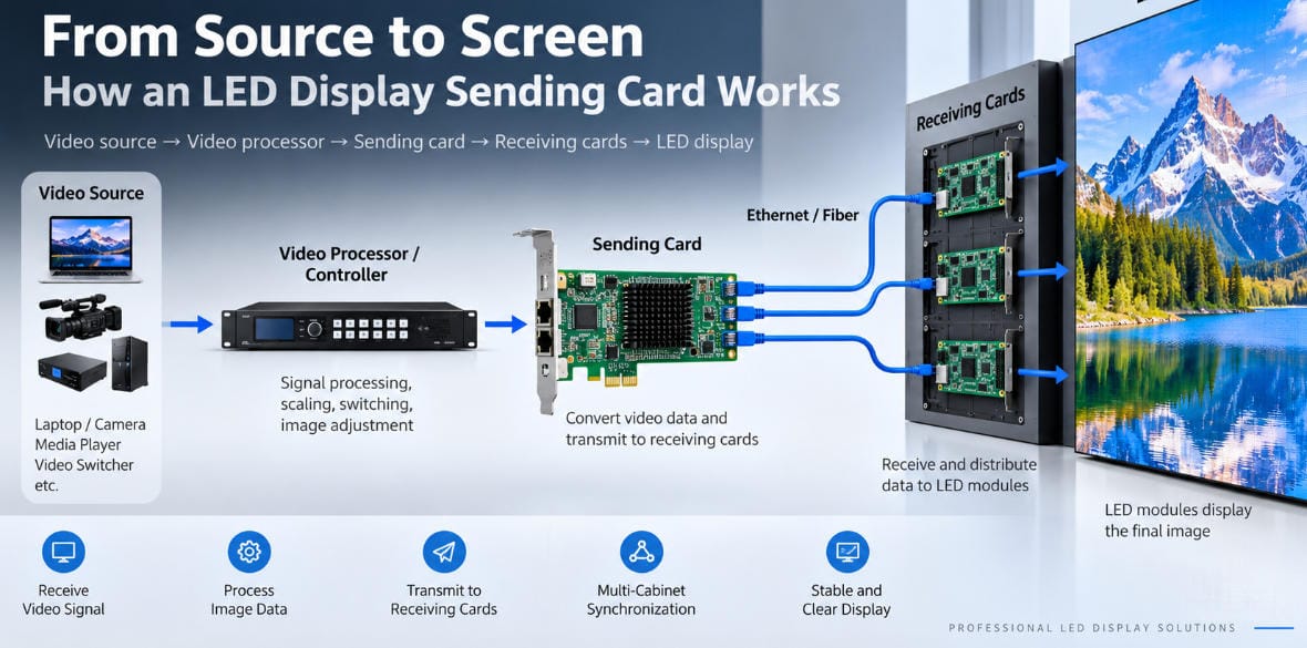
A simplified LED screen signal path is:
Video source → LED controller → receiving card → module driver circuit → LED pixels
The controller processes the incoming video and sends display data to receiving cards installed throughout the screen.
Each receiving card manages a defined section of pixels. It sends the required data and timing signals to the connected modules.
The driver electronics on each module then control the LEDs according to this information.
At the same time, the display’s power supplies convert incoming AC electricity into the low-voltage DC power needed by the modules and control electronics. Meitec’s LED display power supply guide explains this part of the system in more detail.
This means an LED module should not be evaluated independently from the rest of the screen. Module design, receiving-card configuration, power system, driver ICs, and control parameters must operate together.
LED Module vs. LED Cabinet
These two terms are often confused.
An LED module is the smaller display unit containing pixels and electronic components.
An LED cabinet is a larger mechanical assembly that holds several LED modules together with components such as:
- Receiving cards
- Power supplies
- HUB boards
- Internal cables
- Structural frame
- Connectors
For example, a cabinet might contain four, six, eight, or more LED modules depending on its dimensions and product architecture.
Multiple cabinets are then assembled to create the complete LED display.
The relationship can be summarized as:
LED pixels → LED module → LED cabinet → complete LED screen
This modular architecture allows manufacturers to build displays of many different sizes without manufacturing every screen as one large electronic board.
Module Size and Module Resolution
Two basic specifications should be distinguished when evaluating an LED module.
Physical Module Size
This describes the width and height of the module, normally in millimeters.
Common formats vary significantly by product design.
Module Resolution
Module resolution describes how many pixels are arranged horizontally and vertically.
It is calculated from module dimensions and pixel pitch.
For example, consider a module that is:
320 mm × 160 mm
with a pixel pitch of:
P2.5
The approximate pixel resolution is:
320 ÷ 2.5 = 128 pixels
160 ÷ 2.5 = 64 pixels
Therefore, the module resolution is:
128 × 64 pixels
or:
8,192 pixels per module
This calculation is useful when determining cabinet resolution, total screen resolution, receiving-card loading requirements, and content format.
What Is LED Module Scan Mode?
Many LED module specification sheets list terms such as:
- Static scan
- 1/4 scan
- 1/8 scan
- 1/16 scan
- 1/32 scan
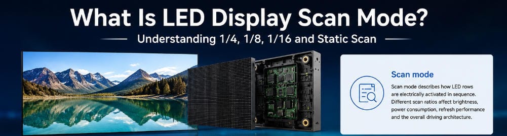
These describe how groups of LED rows are driven electrically.
In a static-drive module, LEDs can be driven continuously without row multiplexing in the same way as higher scan ratios.
In a scanning system, rows are activated sequentially at high speed. Human vision integrates these rapid cycles into a continuous image.
Scan architecture affects circuit design and interacts with brightness, refresh rate, driver IC configuration, and power consumption.
It should therefore not be interpreted simply as “a smaller denominator is always better.”
The correct scan configuration depends on the module design and application.
For a detailed explanation, see Meitec’s guide to LED display scan mode.
SMD LED Modules
SMD, or Surface-Mounted Device, has been widely used in LED display manufacturing.
In a conventional full-color SMD module, packaged LED devices are mounted directly onto the PCB.
Depending on the product, each package commonly integrates red, green, and blue light-emitting elements.
SMD modules are used across a broad range of applications, including:
- Indoor commercial displays
- Outdoor advertising screens
- Rental LED screens
- Stadium displays
- Stage displays
- Large-format video walls
Their mature manufacturing ecosystem and broad range of available pixel pitches make SMD suitable for many conventional LED display applications.
COB Modules and Conventional LED Modules
COB stands for Chip on Board.
Instead of mounting conventional individual SMD LED packages onto the PCB, COB technology places semiconductor chips directly onto the substrate before applying an integrated protective process.
This changes both the packaging structure and surface characteristics of the display.
COB technology is particularly common in fine-pitch and ultra-fine-pitch LED displays, where higher pixel density and surface protection are important.
Potential characteristics of COB displays include:
- Fine pixel pitch
- High pixel density
- Smooth display surface
- Improved resistance to physical contact
- High contrast
- Suitability for short viewing distances
However, COB and SMD should not be treated simply as “new versus old” technologies.
The correct packaging method depends on pixel pitch, application environment, required protection, maintenance strategy, manufacturing process, and project budget.
Indoor vs. Outdoor LED Modules
Indoor and outdoor modules are designed for significantly different operating environments.
Indoor LED Modules
Indoor modules generally prioritize:
- Fine pixel pitch
- Image uniformity
- Viewing comfort
- Color performance
- Low-noise operation
- Close viewing
- Lightweight construction
They normally do not require the same weatherproof structure as outdoor products.
Outdoor LED Modules
Outdoor modules may need to withstand:
- Rain
- Humidity
- Dust
- Direct sunlight
- Temperature changes
- Higher operating brightness
- Long operating periods
Their mechanical construction, sealing, coating, connectors, materials, and heat-management design therefore differ from typical indoor modules.
For example, some outdoor display architectures use enclosed or waterproof module structures to provide additional environmental protection.
Meitec’s Standard LED Displays include indoor and outdoor configurations designed for fixed commercial display applications.
Front-Service and Rear-Service Modules
Maintenance method is another important module-level consideration.
Front-Service Module
A front-service module can be removed from the viewing side of the display.
This is useful when the screen is installed directly against a wall or when there is little maintenance space behind the display.
Magnetic mounting systems are commonly used in some front-service designs.
Rear-Service Module
Rear-service systems are maintained from behind the LED display.
This approach is practical when sufficient service space is available behind the screen.
Neither approach is universally better.
Maintenance design should be determined according to installation conditions, cabinet construction, screen dimensions, and technician access.
Important LED Module Specifications
When comparing LED display modules, pixel pitch alone is not enough.
Important specifications include:
Pixel pitch
Determines pixel density and strongly influences suitable viewing distance.
Module dimensions
Affect cabinet layout and screen geometry.
Module resolution
Determines the number of pixels within each module.
LED packaging technology
May include SMD, COB, or other display packaging approaches.
Brightness
Should match the intended environment rather than simply be maximized.
Scan mode
Defines part of the module’s electrical driving architecture.
Refresh rate
Affects image stability and camera performance, but depends on the complete driving system rather than the module alone.
Grayscale
Influences the number of brightness levels available for color reproduction.
Driver IC
Affects driving performance, refresh capability, grayscale behavior, and other electrical characteristics.
Power consumption
Depends on LED configuration, brightness settings, circuit design, content, and power-management strategy.
Protection level
Especially important for outdoor or demanding installation environments.
Maintenance method
Determines how modules can be removed and replaced.
Evaluating these parameters together provides a more useful picture of real module performance than comparing a single specification.
Why Modules From Different Batches May Look Different
LED displays require strong visual consistency across modules.
However, LED optical characteristics can vary slightly between production batches.
Differences may appear in:
- Brightness
- Color coordinates
- White balance
- LED characteristics
- Component tolerances
Professional manufacturing therefore involves LED selection, production control, module testing, calibration, and screen-level adjustment.
For long-term projects, it is also useful to keep spare modules from the original production batch.
Installing a newly produced replacement module several years later may make color matching more difficult, especially if the original LED components are no longer available.
Calibration can reduce some visible differences, but maintaining compatible spare modules remains an important maintenance strategy.
What Happens When an LED Module Fails?
Module problems can appear in several forms.
Common symptoms include:
- One LED pixel not illuminating
- Individual color channels failing
- A complete row or column behaving abnormally
- Part of the module appearing dark
- Incorrect colors
- Flickering
- An entire module losing its image
- Brightness inconsistency
However, an abnormal module does not always mean the module itself is defective.
The problem may also originate from:
- Loose signal connectors
- Power cables
- HUB boards
- Receiving cards
- Power supplies
- Configuration errors
- Damaged connectors
- Incorrect module parameters
Troubleshooting should therefore follow both the signal path and power path before replacing components.
Can LED Modules Be Replaced Individually?
In most modular LED display designs, yes.
One of the main advantages of modular construction is that technicians can replace a damaged module without replacing the complete screen.
However, the replacement must be electrically and mechanically compatible.
Technicians should verify factors such as:
- Pixel pitch
- Module dimensions
- Resolution
- Connector arrangement
- Scan mode
- Driver IC
- LED type
- Firmware or configuration requirements
- Mounting system
- Production batch or calibration characteristics
A module that has the same physical dimensions is not automatically interchangeable with another module.
How to Choose the Right LED Display Module
For a complete LED display project, selecting a module should begin with the application rather than an isolated module specification.
Important questions include:
- Is the display installed indoors or outdoors?
- What is the minimum viewing distance?
- What total screen resolution is required?
- What brightness is appropriate for the environment?
- Is the installation permanent or rental?
- Is front maintenance required?
- What refresh rate is needed for the content or camera environment?
- How will heat be managed?
- What environmental protection is required?
- Are compatible spare modules available for future maintenance?
Once these requirements are defined, pixel pitch, packaging technology, module structure, cabinet configuration, control system, and power architecture can be selected together.
Final Summary
An LED display module is the fundamental image-producing building block of a modular LED screen.
It combines LED pixels, PCB circuitry, driver electronics, power connections, and signal interfaces into a standardized unit that can be installed together with other modules inside an LED cabinet.
Module design directly affects important display characteristics such as pixel density, brightness, scan architecture, maintenance method, environmental protection, and system configuration.
However, an LED module should never be evaluated only by pixel pitch or physical size.
Reliable LED display performance depends on how the module works together with the driver IC, receiving card, power supply, control system, cabinet structure, and installation environment.
For engineers, installers, and buyers, understanding these relationships makes it easier to evaluate LED display specifications accurately, troubleshoot problems systematically, and select a display architecture that matches the actual project requirements.