Автор: Техническая команда Meitec
Рецензент: Специалист по светодиодным дисплеям
Категория: Основы продукта
Дата последнего обновления: Сентябрь 2026 года
Приёмная карта для светодиодного дисплея — это ключевой компонент системы управления светодиодным экраном. Устанавливаемая внутри светодиодного шкафа или модульной сборки, она принимает цифровые данные отображения от передающего устройства, обрабатывает эти данные и распределяет необходимые управляющие сигналы на светодиодные модули.
Проще говоря, приёмная карта выступает связующим звеном между контроллером светодиодного дисплея и физическими пикселями на экране.
Без приёмной карты большинство обычных полноцветных светодиодных дисплеев не могут корректно интерпретировать видеоданные, передаваемые системой управления. Понимание принципов работы приёмных карт важно при проектировании, настройке, обслуживании или устранении неисправностей светодиодного дисплея.
Каковы функции приёмной карты светодиодного дисплея?
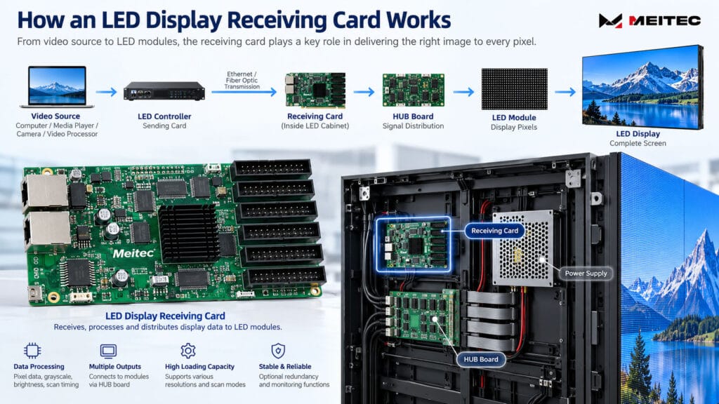
Полная цепочка передачи сигнала светодиодного дисплея обычно включает несколько этапов:
Источник видео → контроллер светодиодного дисплея или передающая карта → кабель передачи данных → приёмная карта → плата HUB или интерфейс модуля → светодиодные модули
Источником видео может быть компьютер, медиаплеер, система камер, видеопроцессор или другое устройство воспроизведения.
Передающее устройство преобразует изображение в данные, которые может передавать система управления светодиодным дисплеем. Эти данные обычно передаются через Ethernet-кабели или волоконно-оптическое оборудование на приёмные карты, установленные по всему светодиодному дисплею.
Каждая приёмная карта управляет определённой группой светодиодных пикселей.
После получения данных карта обрабатывает такую информацию, как:
- Значения цветов пикселей
- Данные яркости
- Информация о градациях серого
- Временные параметры сканирования
- Временные параметры обновления
- Сопоставление модулей
- Коэффициенты калибровки
Затем она формирует электрические управляющие сигналы, необходимые для драйверных микросхем на светодиодных модулях.
Приёмная карта не генерирует видеоконтент самостоятельно. Её задача — корректно принимать, интерпретировать и распределять данные отображения.
Где устанавливается приёмная карта?
Приёмные карты обычно устанавливаются внутри шкафов светодиодных дисплеев.
Типовой шкаф содержит:
- Светодиодные модули
- Блоки питания
- Приёмную карту
- Плату HUB или интегрированную плату распределения сигнала
- Кабели питания
- Кабели передачи данных
В зависимости от архитектуры шкафа одна приёмная карта может управлять всем шкафом, несколькими модулями или определённым участком более крупного шкафа.
В некоторых современных конструкциях светодиодных дисплеев функции приёмной карты и HUB интегрированы в компактные блоки управления. В других используются отдельные приёмные карты, подключаемые к платам HUB через штыревые разъёмы или шлейфы.
Механическая компоновка может различаться, однако базовая функция передачи сигнала остаётся неизменной.
Например, уличный стационарный светодиодный дисплей Meitec MTO Pro Series спроектирован таким образом, что модули, компоненты питания и элементы управления, связанные с приёмной картой, доступны для обслуживания. Его архитектура с фронтальным и тыловым доступом демонстрирует, почему доступность приёмной карты должна учитываться на этапе проектирования шкафа, а не только после установки.
Как работает приёмная карта?
При отображении видео на светодиодном экране изображение разделяется на цифровую информацию о пикселях.
Контроллер светодиодного дисплея определяет, какие пиксели относятся к каждому участку экрана, и отправляет соответствующую информацию через сеть управления.
Приёмная карта получает назначенную ей часть этой информации.
Затем она обрабатывает данные в соответствии с конфигурацией, сохранённой в системе управления, включая физическое расположение светодиодных модулей и электрические характеристики схемы драйверов.
Например, карта должна знать:
- Разрешение модуля
- Количество подключённых модулей
- Схему распределения групп данных
- Режим сканирования
- Тип драйверной микросхемы
- Последовательность каналов RGB
- Ширину и высоту шкафа в пикселях
Если эти параметры заданы неверно, приёмная карта может по-прежнему получать данные, однако изображение может отображаться с искажениями, повторами, смещением, изменением цвета или частичной потерей фрагментов.
Именно поэтому файлы конфигурации приёмных карт имеют важное значение при настройке светодиодного дисплея.
Приёмная карта и передающая карта
Приёмные и передающие карты выполняют различные функции.
A передающая карта или контроллер светодиодного дисплея обычно располагается вблизи источника видеосигнала. Она обрабатывает входящий видеосигнал и передаёт на дисплей данные изображения, адаптированные под светодиодную панель.
A приёмная карта устанавливается внутри светодиодного дисплея и принимает данные, назначенные для её участка экрана.
Таким образом, крупный светодиодный дисплей может использовать один контроллер, но десятки или даже сотни приёмных карт.
Взаимосвязь можно описать следующим образом:
Передающее устройство = распределяет данные экрана
Приёмная карта = управляет локальным участком светодиодного экрана
Некоторые современные контроллеры объединяют функции обработки видеосигнала и передачи данных в одном устройстве, поэтому термин “передающая карта” встречается реже в определённых архитектурах систем. Тем не менее приёмные карты по-прежнему широко используются внутри светодиодных шкафов.
Что такое нагрузочная способность приёмной карты?
Нагрузочная способность является одной из наиболее важных характеристик при выборе или настройке приёмной карты.
Она описывает максимальное количество пикселей, которыми карта может управлять при заданных условиях эксплуатации.
Обычно она выражается как максимальная ширина, максимальная высота или общая ёмкость в пикселях.
Однако нагрузочную способность не следует оценивать простым перемножением двух максимальных значений.
Фактическая ёмкость может зависеть от нескольких факторов, включая:
- Частоту обновления
- глубину градаций серого
- коэффициент сканирования
- Драйверная микросхема
- требования к тактовой частоте данных
- Конфигурацию модулей
- модель приёмной карты
- настройки системы управления
По этой причине теоретическую максимальную нагрузочную способность не следует автоматически рассматривать как рекомендуемую рабочую конфигурацию.
Проектировщик экрана должен проверить нагрузочную способность приёмной карты на соответствие фактическим характеристикам светодиодного модуля и требованиям системы управления.
Пример
Предположим, один шкаф имеет разрешение:
192 × 192 пикселя
Общее количество пикселей составляет:
192 × 192 = 36 864 пикселя
Если приёмная карта поддерживает данное разрешение при требуемой частоте обновления, глубине градаций серого и конфигурации сканирования, одна карта может управлять всем шкафом.
Если разрешение шкафа превышает практическую нагрузочную способность, может потребоваться несколько приёмных карт.
Почему режим сканирования имеет значение
Приёмные карты работают в тесной связи с архитектурой сканирования светодиодного модуля.
Распространённые режимы сканирования светодиодных дисплеев включают:
- Статическое сканирование
- Сканирование 1/2
- Сканирование 1/4
- Сканирование 1/8
- Сканирование 1/16
- Сканирование 1/32
- более высокие коэффициенты сканирования на некоторых дисплеях с малым шагом пикселя
Приёмная карта должна выдавать правильную последовательность управления для схемы драйвера модуля.
Конфигурация, разработанная для модуля со сканированием 1/8, не может быть просто применена к другому модулю без проверки его электрической архитектуры.
Неправильная конфигурация сканирования может привести к дублированию строк, пропаданию линий, аномальной яркости, мерцанию или нечитаемому изображению.
Именно по этой причине такие характеристики, как режим сканирования, частота обновления и глубина градаций серого, следует оценивать как части единой системы управления, а не как полностью независимые значения.
Дополнительные технические статьи, посвящённые данным параметрам дисплея, см. в базе знаний Meitec LED Display.
Что такое HUB-плата?
HUB-плата часто используется между приёмной картой и светодиодными модулями.
Её основное назначение — распределение сигналов.
Приёмная карта обрабатывает данные дисплея, а HUB-плата направляет выходные сигналы на соответствующие разъёмы модулей.
В зависимости от архитектуры светодиодного дисплея HUB-плата может распределять:
- сигналы данных RGB
- тактовые сигналы
- сигналы защёлки (latch)
- Сигналы разрешения вывода
- Сигналы выбора строк
Использование стандартизированной платы HUB позволяет упростить монтаж кабинета и облегчить замену компонентов.
Некоторые более новые конструкции кабинетов интегрируют больше функций управления и мониторинга в архитектуру HUB, что снижает сложность кабельной разводки.
Приёмную карту и плату HUB не следует рассматривать как один и тот же компонент, даже несмотря на их тесную взаимосвязь.
Каковы основные технические характеристики приёмной карты?
При оценке приёмной карты светодиодного дисплея особенно важны несколько характеристик.
1. Максимальная нагрузка
Данный параметр определяет, каким количеством пикселей может управлять карта.
Более высокое разрешение кабинета, особенно в светодиодных дисплеях с малым шагом пикселя, как правило, требует более тщательного планирования нагрузки.
2. Поддерживаемые режимы сканирования
Карта должна поддерживать архитектуру сканирования, используемую светодиодным модулем.
3. Выходы данных
Приёмные карты обеспечивают несколько выходных групп, которые передают данные на светодиодные модули.
Требуемое количество зависит от конструкции модуля и разрешения кабинета.
4. Поддержка частоты обновления и уровня серого
Приёмная карта участвует в архитектуре управления, определяющей способ обработки данных изображения.
Однако сама по себе приёмная карта не гарантирует конкретную частоту обновления или уровень серого. Драйверные микросхемы, конструкция модуля, коэффициент сканирования, конфигурация контроллера и другие параметры системы также влияют на конечные характеристики.
5. Поддержка калибровки
Профессиональные светодиодные системы могут хранить коэффициенты калибровки яркости и цветности.
Приёмные карты, поддерживающие калибровочные данные, способствуют поддержанию более стабильной яркости и цвета между модулями или кабинетами.
6. Функции мониторинга
В зависимости от системы управления и аппаратной конструкции приёмные карты могут поддерживать мониторинг таких параметров, как:
- Температура кабинета
- Состояние питания
- Напряжение
- Состояние связи
- Аппаратные сбои
Эти функции особенно полезны для крупных стационарных установок, где техническим специалистам требуется централизованная диагностика системы.
Что такое резервирование приёмной карты?
Резервирование приёмной карты применяется в приложениях, где надёжность сигнала имеет особое значение.
Вместо использования единственного пути передачи данных резервная система может обеспечивать запасной путь сигнала или резервную архитектуру приёмной карты.
Если основной канал связи выходит из строя, резервный путь может помочь поддерживать работу дисплея в зависимости от конкретной конструкции системы.
Это особенно актуально для:
- Диспетчерские
- Телевизионных сред
- Командные центры
- Транспортные системы
- Мероприятия прямого эфира с высокой ценностью
- Критически важные системы визуализации
Например, проект диспетчерской компании Meitec с использованием серии NOC Pro включает двойное резервирование приёмных карт наряду с двойным резервированием питания, поскольку светодиодная стена рассчитана на непрерывную работу.
Резервирование требуется не для каждого светодиодного дисплея. Его следует выбирать в зависимости от последствий прерывания работы системы и требований к надёжности конкретного применения.
Как подключаются приёмные карты?
Приёмные карты обычно подключаются по последовательной цепочке (daisy-chain).
Типичный путь сигнала может выглядеть следующим образом:
Контроллер → Кабинет 1 → Кабинет 2 → Кабинет 3 → Кабинет 4
Каждый кабинет получает данные, относящиеся к назначенной ему области экрана, одновременно передавая данные связи следующему кабинету.
Между кабинетами обычно используются кабели Ethernet.
Для передачи на большие расстояния между диспетчерской и светодиодным дисплеем могут использоваться оптоволоконные преобразователи или системы управления на основе оптоволокна до момента локального распределения сигнала.
Правильное сопоставление кабинетов имеет решающее значение. Если физический порядок подключения не соответствует программной конфигурации, части изображения могут отображаться в неправильном положении.
Что происходит при выходе из строя приёмной карты?
Проблемы с приёмной картой обычно затрагивают большую область отображения, чем отказы отдельных светодиодов или драйверных ИС.
К распространённым симптомам относятся:
- Полное отсутствие изображения на одном шкафу
- Погасание нескольких модулей в пределах одной управляемой зоны
- Аномальное или искажённое содержимое
- Некорректные цвета
- Повторяющиеся фрагменты изображения
- Периодическое мерцание
- Потеря связи со шкафом
- Шкафы после определённой точки в цепи передачи сигнала теряют данные
Однако эти симптомы не являются автоматическим доказательством неисправности самой приёмной карты.
Аналогичные проблемы могут быть вызваны:
- Ослаблением кабелей Ethernet
- Повреждением сетевых кабелей
- Неисправностью плат HUB
- Некорректными файлами конфигурации
- Проблемами с блоком питания
- Некачественными разъёмами
- Неправильными параметрами модулей
- Прерываниями в цепи передачи данных
Поэтому диагностика должна проводиться систематически по пути прохождения сигнала.
Базовая диагностика приёмной карты
При потере изображения на шкафу технические специалисты могут начать с нескольких проверок.
Во-первых, необходимо убедиться, что приёмная карта получает питание.
Далее следует проверить индикаторы связи и кабели передачи данных. Если несколько нижестоящих шкафов также отключены, необходимо проверить сигнальный кабель, входящий в первый затронутый шкаф.
Если связь выглядит нормальной, но содержимое отображения некорректно, необходимо проверить конфигурацию приёмной карты и параметры модулей.
Заведомо исправный кабель Ethernet или приёмная карта также могут использоваться для сравнения, где это уместно.
Перед заменой оборудования необходимо сохранить исходную конфигурацию и подтвердить совместимость заменяющей карты с существующей системой управления.
Следует избегать случайной загрузки файлов конфигурации с другого светодиодного экрана. Два дисплея могут использовать внешне похожие модули, но иметь разные методы сканирования, драйверные ИС или схемы сигнальных подключений.
Как выбрать правильную приёмную карту
Приёмная карта, как правило, должна выбираться как часть общей архитектуры управления светодиодным дисплеем, а не только по цене или максимальной ёмкости по пикселям.
Important factors include: — К важным факторам относятся:
- Разрешение светодиодного модуля
- Разрешение шкафа
- Метод сканирования
- Драйверная микросхема
- Требуемая частота обновления
- Требуемая градация яркости (серого)
- Требования к калибровке
- Требования к мониторингу
- Требования к резервированию
- Совместимость с системой управления
- Метод технического обслуживания
Для существующего светодиодного дисплея обычно наиболее безопасно использовать модель приёмной карты и конфигурацию, указанные производителем дисплея, если совместимая замена не была технически проверена.
Для нового проекта производитель светодиодного дисплея или системный интегратор должен рассчитать нагрузку на приёмные карты совместно с проектированием модулей и шкафов.
Влияет ли приёмная карта на качество изображения светодиодного дисплея?
Да, но не самостоятельно.
Приёмная карта является частью цепи управления дисплеем, поэтому её вычислительная способность и конфигурация влияют на то, насколько корректно данные изображения достигают светодиодных модулей.
Однако качество изображения определяется всей системой в целом.
Important factors include: — К важным факторам относятся:
- качество светодиодов
- Драйверная микросхема
- Проектирование печатных плат
- Режим сканирования
- Приёмную карту
- Контроллер
- Частоту обновления
- Обработка градаций серого
- калибровку
- Качество исходного видеосигнала
Таким образом, замена приёмной карты на модель с более высокими техническими характеристиками не приводит автоматически к улучшению работы экрана, если светодиодные модули или архитектура драйверов не способны обеспечить требуемую производительность.
Профессиональный светодиодный дисплей должен быть спроектирован как единая согласованная система.
Итоговое резюме
Приёмная карта светодиодного дисплея получает данные изображения от контроллера светодиодного экрана и преобразует их в управляющие сигналы, необходимые для работы светодиодных модулей.
Она определяет, какая часть изображения отображается конкретным шкафом или участком экрана, и работает совместно с HUB-платой, драйверными ИМС, модулями и передающей системой.
При оценке приёмной карты наиболее важными критериями являются не просто бренд или максимальная ёмкость по пикселям. Необходимо учитывать совместимость с разрешением шкафа, режимом сканирования, драйверной ИМС, требованиями к частоте обновления, калибровкой, мониторингом и резервированием.
Для обслуживающего персонала понимание принципов работы приёмной карты также упрощает диагностику неисправностей, поскольку отказ на уровне шкафа часто можно системно отследить по этапам: питание, связь, приёмная карта, HUB-плата и модуль.
В правильно спроектированном светодиодном дисплее приёмная карта может быть физически небольшой, однако она является одним из наиболее важных компонентов, связывающих цифровые видеоданные с фактическими светодиодными пикселями.
Часто задаваемые вопросы
Требуется ли приёмная карта для каждого шкафа светодиодного дисплея?
Не обязательно. Одна приёмная карта может управлять одним шкафом, несколькими небольшими шкафами или частью шкафа с высоким разрешением — в зависимости от нагрузочной способности и архитектуры системы.
Можно ли смешивать приёмные карты разных производителей в одном светодиодном дисплее?
Как правило, это не рекомендуется, если только совместимость не была подтверждена поставщиком системы управления или производителем светодиодного дисплея. Протоколы связи, программное обеспечение, конфигурационные файлы и поддерживаемые функции могут различаться.
Хранит ли приёмная карта видеоконтент?
Обычно нет. Её основная функция — приём и обработка данных отображения. Хранение контента, как правило, обеспечивается медиаплеером, компьютером, контроллером или устройством асинхронного воспроизведения.
Может ли приёмная карта повысить частоту обновления?
Приёмная карта входит в состав системы управления, однако частота обновления также зависит от драйверной ИМС, схемы модуля, коэффициента сканирования, настроек градаций серого и конфигурации системы. Замена только приёмной карты не гарантирует повышения частоты обновления.
Сколько приёмных карт необходимо для светодиодного экрана?
Количество зависит главным образом от общего разрешения экрана, разрешения шкафа, нагрузочной способности приёмной карты и архитектуры системы. Расчёт должен выполняться на этапе проектирования системы управления, а не исходя только из физических размеров экрана.