Autor: Equipo Técnico de Meitec
Revisado por: Especialista en Productos de Pantallas LED
Categoría: Fundamentos del Producto
Última actualización: Septiembre de 2026
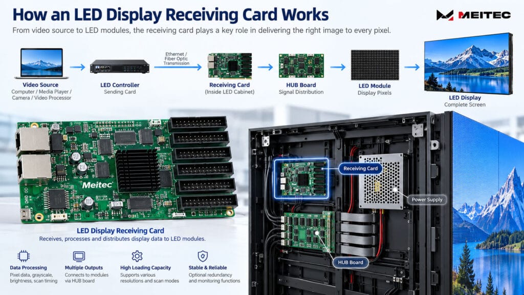
Una tarjeta receptora para pantalla LED es un componente clave del sistema de control de una pantalla LED. Instalada dentro de un gabinete o ensamblaje de módulos LED, recibe los datos digitales de visualización del dispositivo emisor, procesa dichos datos y distribuye las señales de control necesarias a los módulos LED.
En términos simples, la tarjeta receptora actúa como el enlace entre el controlador de la pantalla LED y los píxeles físicos en la pantalla.
Sin una tarjeta receptora, la mayoría de las pantallas LED full-color convencionales no pueden interpretar correctamente los datos de video transmitidos por el sistema de control. Por lo tanto, comprender cómo funcionan las tarjetas receptoras es importante al diseñar, configurar, mantener o solucionar problemas de una pantalla LED.
¿Qué hace una tarjeta receptora para pantalla LED?
Una cadena de señal completa de una pantalla LED normalmente incluye varias etapas:
Fuente de video → Controlador LED o tarjeta emisora → Cable de datos → Tarjeta receptora → Placa HUB o interfaz de módulo → Módulos LED
La fuente de video puede ser una computadora, reproductor multimedia, sistema de cámaras, procesador de video u otro dispositivo de reproducción.
El dispositivo emisor convierte la imagen en datos que el sistema de control de la pantalla LED puede transmitir. Estos datos generalmente viajan a través de cables Ethernet o equipos de transmisión por fibra óptica hasta las tarjetas receptoras instaladas en toda la pantalla LED.
Cada tarjeta receptora controla un grupo definido de píxeles LED.
Después de recibir los datos, la tarjeta procesa información como:
- Valores de color de píxeles
- Datos de brillo
- Información de escala de grises
- Temporización de escaneo
- Temporización de actualización
- Mapeo de módulos
- Coeficientes de calibración
Luego genera las señales de control eléctrico requeridas por los circuitos integrados de control (driver ICs) en los módulos LED.
La tarjeta receptora no genera el contenido de video por sí misma. Su función es recibir, interpretar y distribuir correctamente los datos de visualización.
¿Dónde se instala la tarjeta receptora?
Las tarjetas receptoras normalmente se instalan dentro de los gabinetes de las pantallas LED.
Un gabinete típico contiene:
- Módulos LED
- Fuentes de alimentación
- Tarjeta receptora
- Placa HUB o placa integrada de distribución de señales
- Cables de alimentación
- Cables de datos
Dependiendo de la arquitectura del gabinete, una tarjeta receptora puede controlar todo el gabinete, varios módulos o una sección definida de un gabinete más grande.
Algunos diseños modernos de pantallas LED integran la tarjeta receptora y las funciones HUB en ensamblajes de control compactos. Otros utilizan tarjetas receptoras separadas conectadas a placas HUB mediante conectores de pines o cables planos.
La disposición mecánica varía, pero la función básica de la señal sigue siendo la misma.
Por ejemplo, la Meitec MTO Pro Series Outdoor Fixed LED Display está diseñada para que los módulos, los componentes de alimentación y los componentes de control relacionados con la tarjeta receptora sean accesibles durante el mantenimiento. Su arquitectura de servicio frontal y trasero ilustra por qué la accesibilidad de la tarjeta receptora debe considerarse durante el diseño del gabinete y no solo después de la instalación.
¿Cómo funciona una tarjeta receptora?
Cuando se muestra un video en una pantalla LED, la imagen se divide en información digital de píxeles.
El controlador LED determina qué píxeles pertenecen a cada sección de la pantalla y envía la información correspondiente a través de la red de control.
La tarjeta receptora recibe la porción asignada de esa información.
Luego procesa los datos de acuerdo con la configuración almacenada en el sistema de control, incluida la disposición física de los módulos LED y las características eléctricas del circuito de control.
Por ejemplo, la tarjeta debe conocer:
- Resolución del módulo
- Número de módulos conectados
- Disposición de los grupos de datos
- Modo de escaneo
- Tipo de circuito integrado de control (driver IC)
- Secuencia de canales RGB
- Ancho y alto del gabinete en píxeles
Si estos parámetros son incorrectos, la tarjeta receptora puede seguir recibiendo datos, pero la imagen puede aparecer distorsionada, repetida, desplazada, decolorada o parcialmente ausente.
Esta es la razón por la cual los archivos de configuración de la tarjeta receptora son importantes durante la puesta en marcha de la pantalla LED.
Tarjeta receptora vs. Tarjeta emisora
Las tarjetas receptoras y las tarjetas emisoras realizan funciones diferentes.
A tarjeta emisora o controlador LED normalmente se ubica cerca de la fuente de video. Procesa la señal de video entrante y envía datos de imagen específicos para LED hacia la pantalla.
A tarjeta receptora se instala dentro de la pantalla LED y recibe los datos asignados a su sección de la pantalla.
Una pantalla LED grande puede, por lo tanto, utilizar un controlador pero docenas o incluso cientos de tarjetas receptoras.
La relación puede resumirse como:
Dispositivo emisor = distribuye los datos de la pantalla
Tarjeta receptora = controla una sección local de la pantalla LED
Algunos controladores modernos integran el procesamiento de video y las funciones de emisión en una sola unidad, por lo que el término “tarjeta emisora” es menos común en ciertas arquitecturas de sistema. Sin embargo, las tarjetas receptoras siguen siendo ampliamente utilizadas dentro de los gabinetes LED.
¿Qué es la capacidad de carga de una tarjeta receptora?
La capacidad de carga es una de las especificaciones más importantes al seleccionar o configurar una tarjeta receptora.
Describe el número máximo de píxeles que la tarjeta puede controlar bajo condiciones operativas especificadas.
Comúnmente se expresa como un ancho máximo, una altura máxima o una capacidad total de píxeles.
Sin embargo, la capacidad de carga no debe evaluarse únicamente multiplicando dos números máximos.
La capacidad real puede depender de varios factores, incluyendo:
- Frecuencia de actualización
- Profundidad de escala de grises
- Relación de escaneo
- Circuito integrado del driver
- Requisitos de reloj de datos
- Configuración de módulos
- Modelo de tarjeta receptora
- Configuraciones del sistema de control
Por esta razón, la capacidad máxima teórica de carga no debe tratarse automáticamente como la configuración operativa recomendada.
El diseñador de la pantalla debe verificar la capacidad de la tarjeta receptora contra la especificación real del módulo LED y los requisitos del sistema de control.
Ejemplo
Supongamos que un gabinete tiene una resolución de:
192 × 192 píxeles
El número total de píxeles es:
192 × 192 = 36,864 píxeles
Si la tarjeta receptora soporta esta resolución bajo la tasa de refresco, escala de grises y configuración de escaneo requeridas, una tarjeta puede controlar el gabinete completo.
Si la resolución del gabinete excede la capacidad práctica de carga, pueden requerirse múltiples tarjetas receptoras.
Por qué el modo de escaneo es importante
Las tarjetas receptoras trabajan en estrecha relación con la arquitectura de escaneo del módulo LED.
Los modos de escaneo comunes de pantallas LED incluyen:
- Escaneo estático
- Escaneo 1/2
- Escaneo 1/4
- Escaneo 1/8
- Escaneo 1/16
- Escaneo 1/32
- Relaciones de escaneo más altas en algunas pantallas de paso fino
La tarjeta receptora debe emitir la secuencia de control correcta para el circuito del driver del módulo.
Una configuración diseñada para un módulo de escaneo 1/8 no puede simplemente aplicarse a un módulo diferente sin verificar su arquitectura eléctrica.
Una configuración de escaneo incorrecta puede causar filas duplicadas, líneas faltantes, brillo anormal, parpadeo o una imagen ilegible.
Esta relación es también la razón por la cual especificaciones como el modo de escaneo, la tasa de refresco y la escala de grises deben evaluarse como partes de un mismo sistema de control, en lugar de como valores completamente independientes.
Para artículos técnicos adicionales que cubran estos parámetros de pantalla, consulte la Base de conocimientos de pantallas LED de Meitec.
¿Qué es una placa HUB?
Una placa HUB se utiliza a menudo entre la tarjeta receptora y los módulos LED.
Su propósito es principalmente la distribución de señales.
La tarjeta receptora procesa los datos de la pantalla, mientras que la placa HUB enruta las señales de salida hacia los conectores apropiados del módulo.
Dependiendo de la arquitectura de la pantalla LED, la placa HUB puede distribuir:
- Señales de datos RGB
- Señales de reloj
- Señales de latch
- Señales de habilitación de salida
- Señales de selección de fila
El uso de una placa HUB estandarizada puede simplificar el cableado del gabinete y facilitar el reemplazo de componentes.
Algunos diseños de gabinetes más recientes integran más funciones de control y monitoreo en la arquitectura HUB, lo que reduce la complejidad del cableado.
La tarjeta receptora y la placa HUB no deben tratarse como el mismo componente, aunque estén estrechamente conectadas.
¿Cuáles son las principales especificaciones de una tarjeta receptora?
Al evaluar una tarjeta receptora para pantallas LED, varias especificaciones son particularmente importantes.
1. Capacidad de carga
Esto determina cuántos píxeles puede controlar la tarjeta.
Las resoluciones de gabinete más altas, especialmente en pantallas LED de paso fino, generalmente requieren una planificación de capacidad más cuidadosa.
2. Modos de escaneo compatibles
La tarjeta debe ser compatible con la arquitectura de escaneo utilizada por el módulo LED.
3. Salidas de datos
Las tarjetas receptoras proporcionan múltiples grupos de salida que transmiten datos a los módulos LED.
El número requerido depende del diseño del módulo y de la resolución del gabinete.
4. Soporte de frecuencia de actualización y escala de grises
La tarjeta receptora participa en la arquitectura de control que determina cómo se procesan los datos de imagen.
Sin embargo, una tarjeta receptora por sí sola no garantiza una frecuencia de actualización o un nivel de escala de grises específicos. Los circuitos integrados de control, el diseño del módulo, la relación de escaneo, la configuración del controlador y otros parámetros del sistema también afectan el rendimiento final.
5. Soporte de calibración
Los sistemas LED profesionales pueden almacenar coeficientes de calibración de brillo y cromaticidad.
Las tarjetas receptoras que admiten datos de calibración pueden ayudar a mantener una mayor consistencia de brillo y color entre módulos o gabinetes.
6. Funciones de monitoreo
Dependiendo del sistema de control y del diseño del hardware, las tarjetas receptoras pueden admitir el monitoreo de parámetros tales como:
- Temperatura del gabinete
- Estado de la alimentación
- Voltaje
- Estado de la comunicación
- Fallas de hardware
Estas funciones son particularmente útiles para instalaciones fijas de gran tamaño donde los técnicos necesitan diagnósticos centralizados del sistema.
¿Qué es la redundancia de tarjetas receptoras?
La redundancia de tarjetas receptoras se utiliza en aplicaciones donde la confiabilidad de la señal es especialmente importante.
En lugar de depender de una única ruta de datos, un sistema redundante puede proporcionar una ruta de señal de respaldo o una arquitectura de tarjeta receptora alternativa.
Si la ruta de comunicación principal experimenta una falla, la ruta de respaldo puede ayudar a mantener la operación de la pantalla dependiendo del diseño específico del sistema.
Esto es particularmente relevante para:
- Salas de control
- Entornos de transmisión
- Centros de comando
- Sistemas de transporte
- Eventos en vivo de alto valor
- Sistemas de visualización de misión crítica
Por ejemplo, el proyecto de sala de control de Meitec que utiliza la serie NOC Pro incorpora redundancia dual de tarjetas receptoras junto con respaldo de alimentación dual, porque la pared LED está diseñada para operación continua.
La redundancia no es necesaria para todas las pantallas LED. Debe seleccionarse de acuerdo con las consecuencias de una interrupción del sistema y los requisitos de confiabilidad de la aplicación.
¿Cómo se conectan las tarjetas receptoras?
Las tarjetas receptoras se conectan comúnmente en una red en cadena tipo margarita.
Una ruta de señal típica puede verse así:
Controlador → Gabinete 1 → Gabinete 2 → Gabinete 3 → Gabinete 4
Cada gabinete recibe los datos relevantes para el área de pantalla que le corresponde, mientras transmite los datos de comunicación al siguiente gabinete.
Los cables Ethernet se utilizan comúnmente entre gabinetes.
Para transmisiones de larga distancia, se pueden utilizar convertidores de fibra óptica o sistemas de control basados en fibra entre la sala de control y la pantalla LED antes de que la señal se distribuya localmente.
El mapeo correcto de gabinetes es esencial. Si el orden de conexión física no coincide con la configuración del software, partes de la imagen pueden aparecer en la posición incorrecta.
¿Qué sucede si falla una tarjeta receptora?
Los problemas de la tarjeta receptora generalmente afectan un área de visualización más grande que las fallas individuales de LED o circuitos integrados de driver.
Los síntomas comunes incluyen:
- Un gabinete completo sin mostrar imagen
- Varios módulos dentro de un área controlada que se ponen en negro
- Contenido anormal o distorsionado
- Colores incorrectos
- Secciones de imagen repetidas
- Parpadeo intermitente
- Pérdida de comunicación con un gabinete
- Gabinetes después de un punto en la cadena de señal que pierden datos
Sin embargo, estos síntomas no demuestran automáticamente que la tarjeta receptora en sí esté defectuosa.
Problemas similares pueden ser causados por:
- Cables Ethernet flojos
- Cables de red dañados
- Placas HUB defectuosas
- Archivos de configuración incorrectos
- Problemas de fuente de alimentación
- Conectores deficientes
- Parámetros de módulo incorrectos
- Interrupciones en la cadena de datos
Por lo tanto, la resolución de problemas debe seguir sistemáticamente la ruta de la señal.
Resolución de problemas básicos de la tarjeta receptora
Cuando un gabinete pierde su imagen, los técnicos pueden comenzar con varias verificaciones.
Primero, verifique que la tarjeta receptora tenga alimentación eléctrica.
A continuación, inspeccione los indicadores de comunicación y los cables de datos. Si varios gabinetes posteriores también están fuera de línea, verifique el cable de señal que ingresa al primer gabinete afectado.
Si la comunicación parece normal pero el contenido mostrado es incorrecto, verifique la configuración de la tarjeta receptora y los parámetros del módulo.
También se puede utilizar un cable Ethernet o una tarjeta receptora que se sepa que funcionan correctamente para comparación cuando sea apropiado.
Antes de reemplazar hardware, guarde la configuración original y confirme que la tarjeta de reemplazo sea compatible con el sistema de control existente.
Evite cargar aleatoriamente archivos de configuración de otra pantalla LED. Dos pantallas pueden utilizar módulos de apariencia similar pero tener diferentes métodos de escaneo, circuitos integrados de driver o asignaciones de señal.
Cómo elegir la tarjeta receptora adecuada
La tarjeta receptora normalmente debe seleccionarse como parte de la arquitectura completa de control de la pantalla LED, y no comprarse únicamente según el precio o la capacidad máxima de píxeles.
Los factores importantes incluyen:
- Resolución del módulo LED
- Resolución del gabinete
- Método de escaneo
- Circuito integrado del driver
- Frecuencia de actualización requerida
- Rendimiento de escala de grises requerido
- Requisitos de calibración
- Requisitos de monitoreo
- Requisitos de redundancia
- Compatibilidad con el sistema de control
- Método de mantenimiento
Para una pantalla LED existente, generalmente es más seguro utilizar el modelo de tarjeta receptora y la configuración especificados por el fabricante de la pantalla, a menos que se haya verificado técnicamente un reemplazo compatible.
Para un proyecto nuevo, el fabricante de la pantalla LED o el integrador de sistemas debe calcular la carga de la tarjeta receptora junto con el diseño del módulo y del gabinete.
¿Afecta la tarjeta receptora la calidad de imagen de la pantalla LED?
Sí, pero no de forma independiente.
La tarjeta receptora forma parte de la cadena de accionamiento de la pantalla, por lo que su capacidad de procesamiento y configuración influyen en la correcta transmisión de los datos de imagen a los módulos LED.
Sin embargo, la calidad de imagen está determinada por el sistema completo.
Los factores importantes incluyen:
- calidad del LED
- Circuito integrado del driver
- Diseño del PCB
- Modo de escaneo
- Tarjeta receptora
- Controlador
- Frecuencia de actualización
- Procesamiento de escala de grises
- Calibración
- Calidad de la fuente de video
Por lo tanto, reemplazar una tarjeta receptora con un modelo de especificaciones superiores no mejora automáticamente la pantalla si los módulos LED o la arquitectura de los drivers no pueden soportar el rendimiento deseado.
Una pantalla LED profesional debe estar diseñada como un sistema coordinado en su conjunto.
Resumen final
Una tarjeta receptora de pantalla LED recibe los datos de imagen del controlador LED y los convierte en las señales de control requeridas por los módulos LED.
Determina qué parte de la imagen se muestra en un gabinete o sección de pantalla específico y funciona en conjunto con la placa HUB, los circuitos integrados de driver, los módulos y el sistema de envío.
Al evaluar una tarjeta receptora, las consideraciones más importantes no son simplemente la marca o la capacidad máxima de píxeles. Deben considerarse la compatibilidad con la resolución del gabinete, el modo de escaneo, el circuito integrado de driver, los requisitos de actualización, la calibración, el monitoreo y la redundancia.
Para los equipos de mantenimiento, comprender la tarjeta receptora también facilita la resolución de problemas, ya que una falla de visualización a nivel de gabinete a menudo puede rastrearse sistemáticamente a través de las etapas de alimentación, comunicación, tarjeta receptora, placa HUB y módulo.
En una pantalla LED correctamente diseñada, la tarjeta receptora puede ser físicamente pequeña, pero es uno de los componentes más importantes que conecta los datos de video digital con los píxeles LED reales.
Preguntas Frecuentes
¿Se requiere una tarjeta receptora para cada gabinete de pantalla LED?
No necesariamente. Una tarjeta receptora puede controlar un gabinete, varios gabinetes pequeños o parte de un gabinete de alta resolución, dependiendo de la capacidad de carga y la arquitectura del sistema.
¿Se pueden mezclar diferentes marcas de tarjetas receptoras en una misma pantalla LED?
Generalmente no se recomienda, a menos que el proveedor del sistema de control o el fabricante de la pantalla LED hayan verificado la compatibilidad. Los protocolos de comunicación, el software, los archivos de configuración y las funciones compatibles pueden diferir.
¿Una tarjeta receptora almacena el contenido de video?
Normalmente, no. Su función principal es recibir y procesar los datos de visualización. El almacenamiento de contenido generalmente lo gestiona un reproductor multimedia, una computadora, un controlador o un dispositivo de reproducción asíncrona.
¿Puede una tarjeta receptora aumentar la frecuencia de actualización?
La tarjeta receptora contribuye al sistema de control, pero la frecuencia de actualización también depende del circuito integrado de driver, el circuito del módulo, la relación de escaneo, la configuración de escala de grises y la configuración del sistema. Cambiar únicamente la tarjeta receptora no garantiza una mayor frecuencia de actualización.
¿Cuántas tarjetas receptoras necesita una pantalla LED?
El número depende principalmente de la resolución total de la pantalla, la resolución del gabinete, la capacidad de carga de la tarjeta receptora y la arquitectura del sistema. El cálculo debe realizarse durante el diseño del sistema de control, y no basarse únicamente en el tamaño físico de la pantalla.