Author: Meitec Technical Team
Reviewed by: LED Display Product Specialist
Category: Product Basics
Last Updated: September 2026
An LED display sending card is a key component of the LED display control system. Its main job is to receive video data from a computer, video processor, or other image source, process that data, and transmit it to the receiving cards installed inside the LED screen.
Although the sending card is usually hidden inside a controller, video processor, or control computer, it plays an essential role in determining how video information reaches the display.
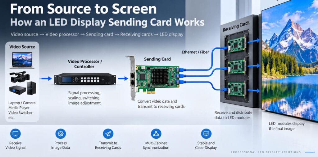
A typical LED display signal chain can be simplified as:
Video source → video processor/controller → sending card → receiving cards → LED modules
If the sending card is incorrectly configured, overloaded, or incompatible with the rest of the control system, the LED display may show only part of the image, display corrupted content, lose signal, or fail to operate correctly.
This guide explains what an LED display sending card does, how it works, how it differs from a receiving card and video processor, and what specifications matter when configuring an LED display system.
What Is a Sending Card in an LED Display?
A sending card is a control device that converts processed image data into a format that can be transmitted through the LED display control network.
It normally receives image information through a computer interface or from an integrated LED controller and then distributes that information through Ethernet or optical connections.
Depending on the control-system manufacturer and product generation, the term may also appear as:
- LED sending card
- sender card
- transmitting card
- LED display transmitter
- sending controller
The exact hardware format varies.
Traditional sending cards may be PCI or PCIe cards installed inside a computer or controller chassis. Modern LED systems increasingly integrate sending functionality directly into standalone controllers and video processors.
For this reason, a modern LED controller may perform the function of a sending card even when there is no separate physical card visible to the user.
What Does an LED Sending Card Do?
The sending card sits between the video-processing stage and the LED display receiving system.
Its main functions include the following.
1. Receiving Image Data
The control system first receives video from a source such as:
- desktop computer
- media player
- camera system
- video switcher
- digital signage player
- video processor
- presentation system
Common source interfaces can include HDMI, DisplayPort, DVI, SDI, or other professional video formats depending on the controller.
The image may first be scaled, cropped, switched, synchronized, or otherwise processed before it reaches the sending stage.
2. Converting the Video Into LED Control Data
An LED module cannot directly interpret a normal HDMI video signal.
The control system must convert the source image into data that corresponds to the physical pixel arrangement of the LED display.
The sending system organizes information according to parameters such as:
- screen resolution
- cabinet arrangement
- receiving-card mapping
- color data
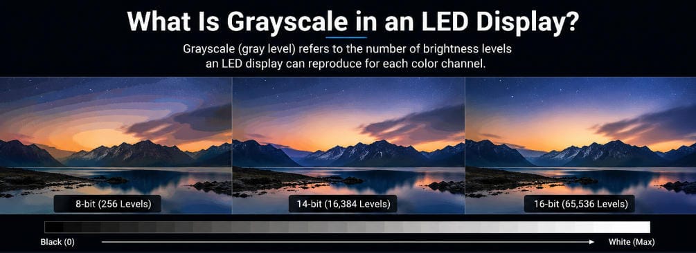
- grayscale information
- synchronization timing
This processed data is then prepared for transmission to the screen.
3. Sending Data to Receiving Cards
The sending card transmits image information through one or more data outputs.
Copper Ethernet connections are widely used for short and medium signal distances, while fiber-optic transmission may be used for longer distances or applications requiring stronger resistance to electromagnetic interference.
Each output has a limited data capacity.
The total LED screen resolution therefore cannot simply be connected to any number of ports without calculation. The pixel load must be distributed according to the capacity of the sending device and its outputs.
4. Maintaining Image Synchronization
A large LED display may contain dozens or hundreds of cabinets.
Each cabinet must display the correct portion of the image at the correct time.
The sending system coordinates data distribution so that all receiving cards operate as part of one synchronized display.
If synchronization fails, visible problems may include tearing, incorrect image positions, duplicated sections, or unstable content.
Sending Card vs. Receiving Card
Sending cards and receiving cards are part of the same control system, but they perform different jobs.
| Component | Sending Card | Receiving Card |
|---|---|---|
| Typical location | Controller, processor, or control computer | Inside LED cabinets |
| Main function | Sends processed image data | Receives and distributes data locally |
| Quantity | Usually one or several | Usually many |
| Controls | Overall signal transmission | Individual cabinet/module sections |
| Connection | Video/control system to screen | Sending system to LED modules |
A useful way to understand the difference is:
The sending card distributes the image to the screen. The receiving card controls how each part of the screen receives that image.
One sending device may communicate with many receiving cards connected in sequence across an LED wall.
Receiving cards then work with HUB boards, driver ICs, and LED modules to reproduce the actual image.
Sending Card vs. Video Processor
These two components are also frequently confused.
A video processor mainly handles the video signal itself.
Its functions may include:
- image scaling
- resolution conversion
- signal switching
- cropping
- multi-window display
- color adjustment
- source management
A sending card focuses on transmitting LED control data to the receiving cards.
Traditionally, these could be two separate pieces of equipment.
For example:
Laptop → video processor → sending card → LED screen
Modern controllers often integrate both functions.
A single device may contain HDMI inputs, video scaling, image switching, screen configuration, and multiple LED network outputs.
In this case, the device is generally called an LED display controller or all-in-one controller, even though sending-card functionality remains part of its internal architecture.
How Does a Sending Card Communicate With the LED Screen?
The most common connection uses Ethernet-style network cables.
However, although standard RJ45 connectors may be used, the signal should not be treated as ordinary office-network traffic.
The ports carry control-system data designed for LED display transmission.
The typical connection is:
Sending device → Ethernet output → first receiving card → next receiving card → additional receiving cards
Multiple Ethernet outputs can divide the screen into different areas.
For example, one output might control the left side of a display while another controls the right side.
The exact loading arrangement depends on:
- total screen resolution
- number of receiving cards
- cabinet resolution
- controller output capacity
- cabling topology
- redundancy requirements
For very large displays, multiple controllers or sending devices may be required.
What Is Sending Card Loading Capacity?
Loading capacity describes how many LED pixels a sending device or individual output can control.
This is one of the most important specifications when designing an LED control system.
Suppose an LED wall has a resolution of:
3840 × 2160 pixels
The total number of pixels is:
3840 × 2160 = 8,294,400 pixels
The selected sending system must therefore support at least this total pixel load while also meeting output-specific limitations.
However, total pixel count is not the only consideration.
Some controllers also specify limits for:
- maximum width
- maximum height
- pixels per Ethernet port
- number of receiving cards per port
- output bandwidth
- supported frame rate
A controller that supports enough total pixels may still be unsuitable if the screen dimensions exceed its maximum width or height.
This is why sending-card selection should be based on the actual screen configuration rather than total megapixels alone.
Why Is Screen Mapping Important?
Every receiving card needs to know which section of the complete image it should display.
Screen mapping defines the relationship between controller outputs, cabinets, receiving cards, and physical screen position.
For example, consider a display arranged as:
8 cabinets wide × 5 cabinets high
The configuration software needs to understand the order in which data cables pass between those cabinets.
If the software assumes the signal travels left-to-right while the physical cable runs in another order, the image can appear scrambled even though every cabinet is functioning correctly.
Correct configuration therefore requires accurate information about:
- cabinet resolution
- cabinet arrangement
- receiving-card order
- port assignment
- cable routing
- module configuration
Many apparent LED display faults are actually configuration or mapping errors rather than hardware failures.
Does a Sending Card Affect Refresh Rate?
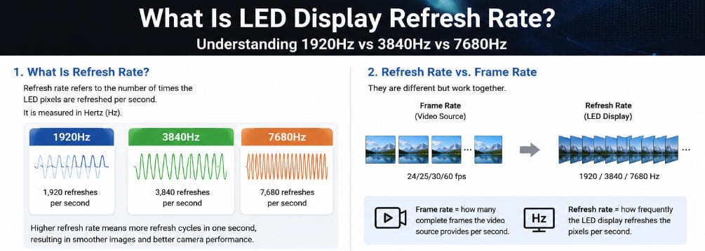
Indirectly, yes, but the sending card is not the only component responsible for refresh rate.
LED display refresh performance depends on the entire control and driving architecture, including:
- sending system
- receiving card
- driver IC
- scan mode
- PWM implementation
- module design
- configuration parameters
The sending system must provide stable and correctly synchronized image data, but installing a higher-capacity sending card does not automatically change a low-refresh LED module into a high-refresh display.
For a more detailed explanation of this parameter, see Meitec’s guide to LED display refresh rate.
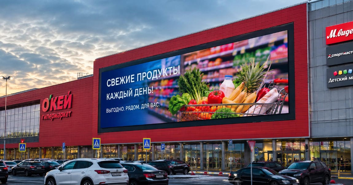
This distinction is particularly important for broadcast, rental, live-event, and camera-facing applications, where several components of the LED system must work together to achieve stable on-camera performance.
What Specifications Matter When Choosing a Sending Card?
When evaluating an LED sending system, focus on system compatibility rather than one headline specification.
Pixel Loading Capacity
Confirm that the controller can handle the complete physical resolution of the display.
Always leave sufficient design margin rather than operating unnecessarily close to the maximum limit.
Number of Outputs
More Ethernet or optical outputs allow higher-resolution screens to be divided across more signal paths.
This can also simplify cabling in large installations.
Maximum Output Width and Height
Some applications use unusually wide or narrow LED displays.
Ribbon screens, digital billboards, stadium fascia displays, and long retail displays can exceed dimension limits even when the total pixel count remains within the controller’s nominal capacity.
Input Interfaces
The available inputs should match the intended content system.
Common requirements include HDMI, DVI, DisplayPort, and SDI.
Professional installations may also require source switching or backup inputs.
Redundancy Support
Mission-critical LED displays may require redundant controllers, backup signal paths, or dual receiving-card systems.
Applications such as command centers, broadcasting, major events, and transportation facilities may prioritize signal continuity more heavily than ordinary commercial signage.
Control-System Compatibility
Sending and receiving equipment should normally belong to a compatible control ecosystem.
Compatibility must be confirmed between:
- controller or sending device
- receiving cards
- firmware
- configuration software
- LED module parameters
Mixing unsupported components can make configuration and troubleshooting unnecessarily difficult.
Common Sending Card Problems
When a sending system is incorrectly configured, several symptoms may appear.
The entire screen is black.
Check the video source, controller output, signal connection, screen configuration, and power status.
Only part of the LED display works.
One controller port may be overloaded, disconnected, incorrectly mapped, or configured with the wrong cabinet count.
The image is scrambled.
The receiving-card connection sequence may not match the screen mapping stored in the configuration.
The same image section repeats.
Cabinet mapping or receiving-card coordinates may be duplicated.
The display intermittently loses signal.
Possible causes include damaged data cables, poor connectors, excessive cable distance, controller problems, unstable receiving cards, or incorrect network topology.
Troubleshooting should therefore follow the complete signal path rather than immediately replacing LED modules.
Do All LED Displays Need a Sending Card?
All synchronous LED displays require sending functionality, but they do not necessarily require a separate physical sending card.
Traditional systems often used an independent sender installed in a computer.
Modern installations frequently use integrated controllers.
For example:
Video source → integrated LED controller → LED cabinets
The controller already contains the sending function.
Some small advertising displays may instead use asynchronous control cards, where content is stored locally and played without a continuously connected video source.
The architecture therefore depends on the application.
Large commercial indoor and outdoor LED displays normally use professional control systems selected according to resolution, installation layout, signal distance, content sources, and operating requirements.
How Should a Sending System Be Selected for an LED Project?
The controller should not be selected in isolation.
Start with the complete display specification:
- Calculate the total screen resolution.
- Determine the resolution of each cabinet.
- Confirm the number and arrangement of receiving cards.
- Calculate the loading requirement for each output.
- Check maximum width and height limitations.
- Confirm required video inputs.
- Determine the signal-transmission distance.
- Decide whether redundancy is necessary.
- Confirm compatibility with the receiving-card system.
- Verify configuration before installation.
For larger projects, this planning should be completed before the LED display is manufactured or installed.
Cable routes, controller location, fiber requirements, backup architecture, power distribution, cabinet layout, and control equipment all influence the final system design.
Meitec approaches professional LED display solutions as complete systems rather than treating the LED cabinets, control hardware, installation, and signal architecture as unrelated components.
Frequently Asked Questions
Is a sending card the same as a controller?
Not always.
A traditional sending card is one component of the control system. A modern LED controller may integrate sending-card functions together with video input, scaling, switching, and other processing features.
Can one sending card control an entire LED wall?
Yes, if the screen resolution and dimensions remain within its loading capacity. Larger LED walls may require additional outputs, controllers, or sending devices.
Can I connect any receiving card to any sending card?
Not necessarily. Sending and receiving hardware must use a compatible control system, firmware, and configuration environment.
Does a better sending card improve LED image quality?
It can improve system capability, stability, synchronization, and processing performance, but image quality also depends on the LED modules, driver ICs, receiving cards, calibration, grayscale, refresh rate, video source, and processing chain.
What happens if the sending card capacity is too small?
The complete screen may not be loadable. Parts of the LED display may remain unused, or the system may require additional ports or controllers.
Final Summary
An LED display sending card is the link between the video control system and the receiving cards inside the LED screen.
Its job is to organize and transmit image data so that every cabinet receives the correct portion of the picture at the correct time.
When selecting a sending system, the important factors are not simply brand or port quantity. Screen resolution, output loading capacity, maximum dimensions, signal distance, receiving-card compatibility, input requirements, system topology, and redundancy must all be considered together.
In modern LED installations, the sending card may no longer exist as a separate visible board. Its function is often integrated into an LED controller or video processor.
Understanding this role makes it easier to design, configure, and troubleshoot the entire LED display signal chain—from the original video source to the pixels on the screen.