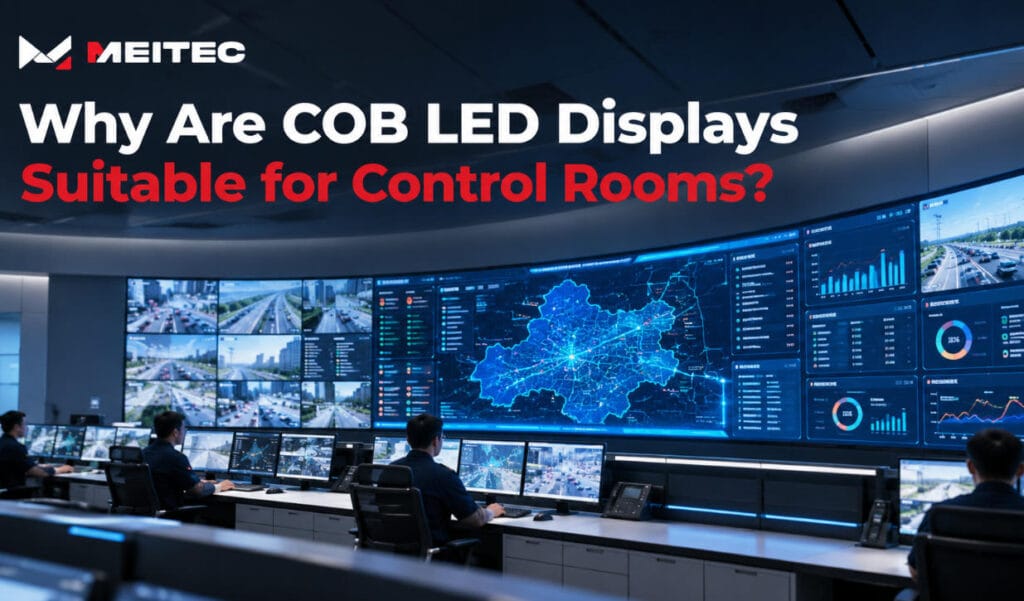
Control rooms depend on large-format displays to present surveillance footage, system alarms, operational dashboards, maps, and real-time data. Unlike conventional presentation screens, these displays may operate continuously while operators monitor information from different positions throughout the room.
COB (Chip-on-Board) LED displays are well suited to these environments because they support fine pixel pitches, protected display surfaces, high-density image reproduction, and optical designs that can improve contrast and reduce reflections.
However, COB packaging alone does not guarantee control-room reliability. The complete display system must also provide appropriate brightness, grayscale performance, calibration, redundant electronics, and accessible maintenance.
Understanding these requirements explains why COB technology is increasingly considered for professional control-room video walls.
1. What Does a Control Room Require From an LED Display?
A control room LED display is an operational visualization system rather than a conventional advertising or presentation screen.
Its primary function is to help operators identify information accurately and respond to changing conditions.
Typical applications include security operations centers, network operations centers, traffic management facilities, energy monitoring centers, emergency command centers, and industrial control rooms.
Although their operating environments differ, these installations share several technical requirements.
| Control Room Requirement | Technical Importance |
|---|---|
| Fine pixel pitch | Supports detailed maps, text, and multiple monitoring windows |
| High contrast | Improves distinction between dark backgrounds and important information |
| Wide viewing angles | Maintains visibility across multiple operator positions |
| Stable grayscale reproduction | Preserves details in dark video and low-brightness graphics |
| Continuous operation | Supports long operating schedules, including 24/7 use |
| Redundant architecture | Reduces vulnerability to selected component failures |
| Service accessibility | Simplifies maintenance and module replacement |
| Power efficiency | Helps control energy demand and cooling requirements |
A suitable display must address these factors together. High resolution is valuable, but it cannot compensate for unreliable power systems, excessive reflections, or poor brightness uniformity.
2. Fine Pixel Pitch Supports Detailed Monitoring
One of the main advantages of COB technology is its suitability for high-density LED packaging.
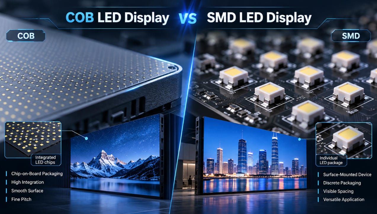
In a COB display, bare LED chips are mounted directly onto a substrate and encapsulated within a protective layer. This structure removes the need for individually packaged SMD LEDs and supports compact pixel arrangements.
For control rooms, higher pixel density is particularly useful because operators often examine detailed information rather than large video images alone.
Typical content includes:
- Small numerical values and equipment labels
- Geographic information system (GIS) maps
- Surveillance footage arranged in multiple windows
- Network topology diagrams
- Monitoring dashboards and alert indicators
Smaller pixel pitches allow more image pixels to fit within a given screen area.
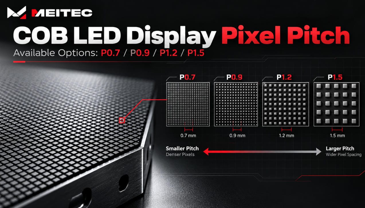
For example, Meitec’s NOC Pro Series includes actual pixel pitches of 0.78125 mm, 0.9375 mm, and 1.25 mm, corresponding to nominal P0.7, P0.9, and P1.2 configurations.
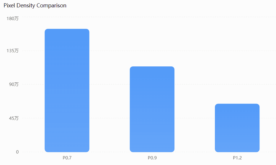
Higher density can improve the reproduction of small text, thin lines, and complex layouts. Nevertheless, it also increases the number of pixels that must be processed and maintained.
The correct pitch depends on the wall dimensions, native resolution, viewing distance, and actual information density.
For a more detailed explanation, see Meitec’s guide to COB LED display pixel pitch options.
3. High Contrast Improves Visibility of Dark Interfaces
Many control-room applications use predominantly dark interfaces.
Security monitoring platforms, network dashboards, industrial SCADA systems, and mapping software frequently combine black or dark-gray backgrounds with colored indicators.
A display with poor black-level performance may make these interfaces appear washed out, especially under ambient lighting.
COB displays can achieve high contrast through a combination of dark encapsulation materials, optimized LED chip structures, and low-reflection surface treatments.
The integrated surface can reduce unwanted reflections compared with designs that expose more reflective areas between individual LED packages.
This is particularly beneficial when operators need to distinguish subtle details in dark video footage.
However, contrast depends on more than packaging technology. Important variables include the encapsulation material, optical treatment, ambient lighting, driver performance, and calibration.
For example, Meitec’s NOC0.9 Pro has a published contrast ratio of 15,000:1. This is a product-specific specification, not a universal performance level for all COB displays.
When evaluating a screen, engineers should verify contrast performance under realistic control-room lighting rather than relying exclusively on laboratory figures.
4. Low Reflection Supports Long Viewing Sessions
Control-room operators may spend several hours observing the same display wall.
In these environments, reflections from ceiling lights, windows, and surrounding equipment can interfere with the visibility of information.
COB displays with properly designed matte or low-reflection encapsulation surfaces can reduce distracting reflections.
This provides practical benefits when the display is installed opposite overhead lighting or viewed from different angles.
Low reflection should not be confused with guaranteed eye comfort.
Visual comfort also depends on screen brightness, viewing distance, ambient illumination, flicker behavior, text size, and work-rest practices.
For continuous monitoring, the display should be adjusted to a comfortable operating brightness rather than simply using its maximum available luminance.
A COB display rated for high brightness is not necessarily intended to operate at that level throughout a normal control-room shift.
5. Wide Viewing Angles Support Multiple Operator Positions
Unlike a private desktop monitor, a control-room video wall is often shared by several operators.
Personnel may view the display from central workstations, side consoles, or supervisory positions.
As viewing angles increase, some display technologies experience brightness reduction, color shift, or lower perceived contrast.
COB technology can support wide viewing angles because its integrated chip structure and optical surface can provide relatively uniform light distribution.
However, actual viewing-angle performance depends on the complete optical design.
Meitec’s NOC Pro Series specifies horizontal and vertical viewing angles of 160°.
For practical evaluation, operators should inspect text, colored indicators, and low-grayscale content from the extreme positions used in the room.
A nominal viewing-angle specification is useful, but it should not replace an on-site visual assessment.
6. Protected COB Surfaces Improve Physical Durability
Traditional SMD LED displays use separately packaged LED components mounted onto a PCB.
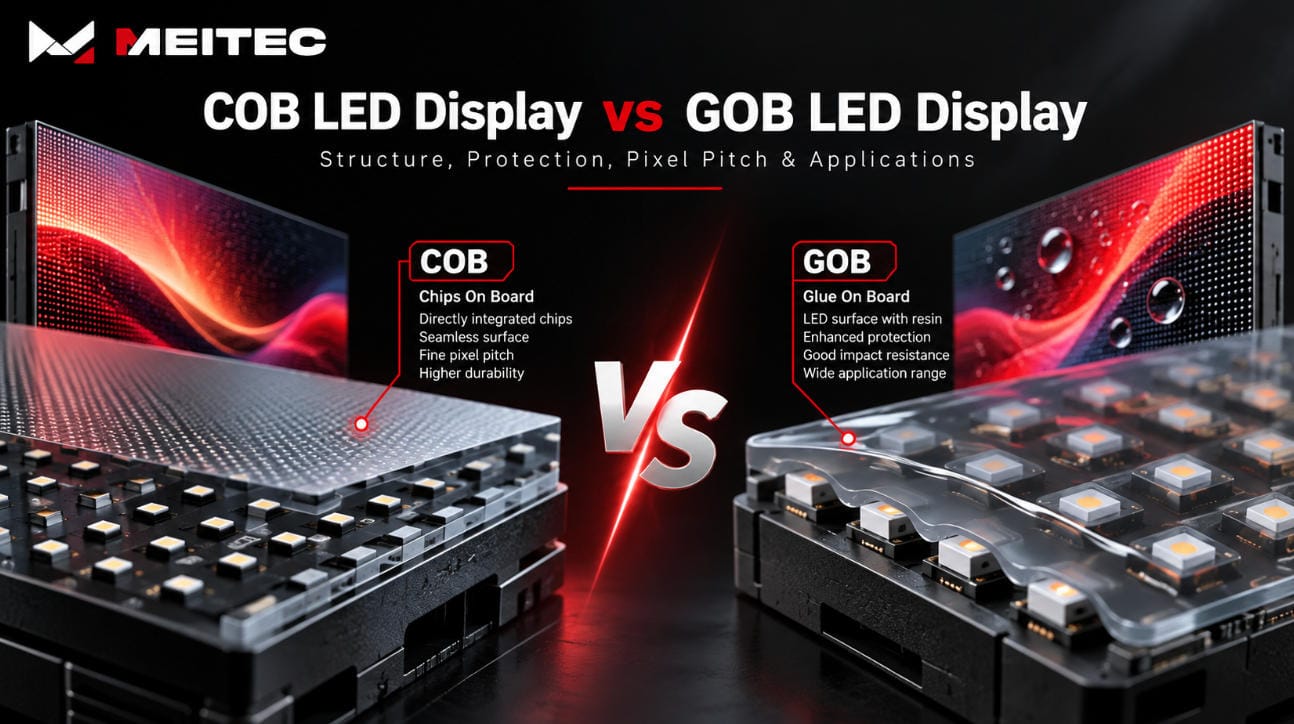
In comparison, COB technology encapsulates the LED chips beneath an integrated protective layer.
This reduces their direct exposure to incidental contact and surface contamination.
For control rooms, where displays are often permanently installed, the main advantage is not frequent physical handling. Instead, the protected surface can simplify cleaning and reduce the risk of damage during inspection and maintenance.
Depending on the encapsulation design, COB technology may improve resistance to minor impact, dust, moisture exposure, and electrostatic contact.
However, protection ratings should be confirmed against individual product specifications.
COB should not automatically be interpreted as waterproof or immune to mechanical damage.
In professional installations, surface protection is one part of the reliability strategy, alongside electrical design and quality control.
7. COB Technology Can Support 24/7 Operation
Many control rooms operate continuously.
A network operations center, for example, may need to display service-status information without interruption. A transportation control center may rely on live visual information during every operating shift.
For these applications, reliability depends on both the LED modules and the supporting electronics.
Full Flip-Chip COB technology can eliminate conventional chip bonding wires, removing failure mechanisms specifically associated with those wire connections.
Its chip-to-substrate electrical and thermal design can also support efficient heat transfer when properly engineered.
However, continuous operation depends on additional components, including power supplies, receiving cards, control processors, cooling systems, and data connections.
A reliable control-room LED wall should therefore be evaluated as an integrated system.
Meitec’s NOC Pro Series COB Micro LED Display is designed for professional continuous-operation environments and includes configurations with redundant power and receiving-card architecture.
Redundancy can reduce selected single points of failure, but its effectiveness depends on the actual system topology and should be verified through failover testing.
For mission-critical applications, operators should also establish procedures for display faults and temporary monitoring alternatives.
8. Lower Power Consumption Can Reduce Long-Term Operating Costs
Electricity consumption becomes particularly important when a large LED video wall operates throughout the year.
The total energy requirement depends on several factors:
- Display surface area
- Average power consumption per square meter
- Daily operating hours
- Typical brightness and displayed content
- Driver efficiency and power architecture
Some COB display systems combine efficient LED chip structures with common-cathode driving technology.
In a common-cathode design, electrical power can be managed more efficiently by supplying appropriate voltage levels to the different LED color channels.
However, common-cathode architecture is not inherent to COB packaging. The two technologies must be evaluated separately.
According to Meitec’s published NOC Pro specifications, average power consumption ranges from approximately 60 to 70 W/m², depending on the model.
As an illustrative calculation, a 10 m² LED wall averaging 65 W/m² and operating 24 hours daily would consume:
\[ 10 \times 65 \times 24 = 15{,}600\text{ Wh/day} \]
This equals 15.6 kWh per day, or approximately 5,694 kWh annually.
The calculation excludes processing equipment, cooling-system overhead, and other infrastructure. Actual consumption changes with image content and operating settings.
For procurement purposes, measured average power under representative control-room content is more meaningful than a theoretical minimum value.
9. Front Maintenance Reduces Service Disruption
A control-room display is frequently installed against a wall, leaving limited access behind the cabinets.
This makes front-service capability particularly valuable.
Front-maintenance LED systems allow technicians to access modules and selected internal components from the viewing side, depending on the cabinet design.
The arrangement can reduce the need for rear service corridors and simplify replacement procedures.
However, COB modules may require specialized repair methods because the LED chips are encapsulated.
While some conventional SMD components can be replaced individually, many COB repairs are more practical at module or factory level.
Therefore, maintenance planning should consider spare module availability, replacement procedures, calibration data, service access, and expected repair turnaround time.
A display with protected LED chips may experience fewer surface-related failures, but this does not eliminate the need for a structured maintenance program.
10. Image Calibration Is Essential for Visual Consistency
A large control-room LED wall may contain hundreds of thousands or millions of individual pixels.
Even when high-quality LED chips are used, variations in their optical output can produce visible brightness or color differences.
These variations can appear as module boundaries, inconsistent white balance, color patches, or uneven grayscale reproduction.
Such inconsistencies become more noticeable when the wall displays uniform backgrounds or dark monitoring interfaces.
LED display calibration measures and corrects differences between individual pixels or display regions.
The process typically involves measuring optical output, calculating correction coefficients, and applying those corrections through the LED control system.
For continuous-operation installations, recalibration may become necessary after module replacement, extended aging, or significant changes in display uniformity.
COB packaging does not remove this requirement.
Meitec explains the process in its technical article on LED display calibration.
11. COB vs. SMD vs. LCD Video Walls for Control Rooms
COB LED displays are not the only available technology for professional control-room visualization.
Fine-pitch SMD LED walls and tiled LCD video walls can also provide reliable results when designed for the application.
| Factor | COB LED Wall | SMD LED Wall | Tiled LCD Wall |
|---|---|---|---|
| Fine-pitch capability | Excellent potential | Good, product-dependent | High native pixel density |
| Visible seams | Minimal with correct alignment | Minimal with correct alignment | Bezel boundaries remain |
| Surface protection | Integrated encapsulation | Depends on package/protection | Front glass or panel surface |
| Contrast | Depends on optical design | Depends on optical design | Depends on LCD panel and backlight |
| Modular maintenance | Usually module-based | Module or component-based | Panel-based |
| Close viewing | Strong at suitable pitch | Strong at suitable pitch | Strong with suitable resolution |
| Overall cost | Often higher initial cost | Wide cost range | Can be economical for some layouts |
The main advantage of direct-view COB LED walls is the combination of fine-pitch image reproduction and a large, nearly seamless visualization surface.
LCD video walls can remain attractive when very high pixel density or established panel-based maintenance is a priority.
SMD displays can offer cost and repairability advantages in certain configurations.
The correct choice depends on the physical environment, required resolution, reliability targets, and total ownership cost.
12. How to Choose a COB LED Display for a Control Room
Choosing a COB display should begin with operational requirements, not with the smallest available pixel pitch.
Determine the required information density
Identify how many video feeds, dashboards, maps, and data windows must appear simultaneously.
Small text and dense interfaces require more native pixels than large video images.
Calculate the native display resolution
Use the planned display dimensions and actual pixel pitch to estimate the available pixel count.
For example, a wall measuring 6 m wide by 3.375 m high with an actual 0.9375 mm pixel pitch provides:
- Horizontal resolution: 6,400 pixels
- Vertical resolution: 3,600 pixels
- Total resolution: approximately 23.04 million pixels
This is a theoretical native-pixel calculation for those dimensions. The actual cabinet layout, processor mapping, and content system must support the intended resolution.
Evaluate the operating environment
Review workstation viewing distances, lighting conditions, reflections, viewing angles, temperature, and available maintenance space.
Confirm system-level reliability
Check power-supply redundancy, receiving-card redundancy, control-system recovery, monitoring functions, and spare parts.
For applications requiring near-continuous availability, request a documented failover demonstration rather than relying exclusively on redundancy claims.
Test representative content
Before final acceptance, display actual control-room interfaces.
Inspect fine text, thin map lines, dark video, alert colors, grayscale gradients, and multi-window arrangements from typical operator positions.
A useful acceptance test should assess not only image sharpness but also visual uniformity, signal recovery, and serviceability.
13. COB LED Displays in Real Control Room Applications
The suitability of COB technology becomes clearer when its technical characteristics are matched with actual operating requirements.
In Meitec’s published control-room project, the display was selected for close viewing, detailed monitoring information, dark-interface visibility, and continuous operation.
The installation used the NOC Pro Full Flip-Chip COB platform, which combines fine pixel pitch with front maintenance and redundant system architecture.
The case illustrates how display selection involves multiple engineering considerations rather than resolution alone.
For application-specific details, see Meitec’s COB LED display control room case study.
COB LED displays are suitable for control rooms because their packaging architecture supports fine pixel pitch, durable display surfaces, and optical designs that can deliver high contrast and low reflections.
These characteristics help reproduce detailed monitoring information while supporting large-format visualization from multiple viewing positions.
For continuous-operation environments, the benefits become most meaningful when combined with reliable electronics, appropriate power efficiency, calibration, redundancy, and accessible maintenance.
The key consideration is therefore not simply whether a display uses COB technology, but whether the complete LED wall meets the operational and visual requirements of the control room.